Walking assistance device

a technology of assistance device and walking aid, which is applied in the field of walking assistance device, can solve the problems of inconvenient restraint for users, inability to accurately detect the tread force of users, and the free movement of feet, etc., and achieve the effect of accurate detection, accurate detection, and accurate detection

Active Publication Date: 2013-05-07
HONDA MOTOR CO LTD
View PDF5 Cites 0 Cited by
  • Summary
  • Abstract
  • Description
  • Claims
  • Application Information

AI Technical Summary

Benefits of technology

[0009]According to the present invention, the connecting member rises in the cantilever manner from one lateral side of the ground contact member, so that a foot of a user is not restrained by the connecting member. As a result, the freedom of foot motions is secured, leading to more comfortable fit of the foot-worn assembly.
[0036]Further, in the present embodiment, the tread plate member 23 is provided with a relief hole 23b for each of the tread force sensors 5, as illustrated in FIG. 3(b). This prevents the upper plate 54 of each of the tread force sensors 5 from interfering with the tread plate member 23. Hence, a force transferred from the leg link 3 to the tread plate member 23 through the intermediary of the connecting member 22 is not input to the tread force sensor 5. As a result, a tread force of the user can be accurately detected without being influenced by a body weight support assisting force to be generated at the leg link 3.

Problems solved by technology

In the stirrup-shaped connecting member of the aforesaid conventional example, a foot of the user is inserted into the connecting member, so that the freedom of the motion of the foot will be limited, thus inconveniently making the user feel restrained.
However, merely securing the freedom of foot motions presents the following problem.
Thus, the tread force sensors provided in only a total of two locations, one adjacent to the heel of a foot and the other adjacent to the toe, as in the aforesaid conventional example, fail to accurately detect the tread forces of the user.

Method used


Image

  • Walking assistance device
  • Walking assistance device
  • Walking assistance device

Examples


Embodiment Construction

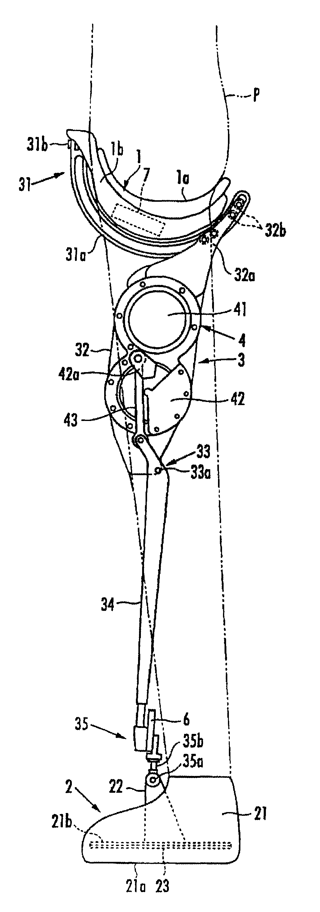
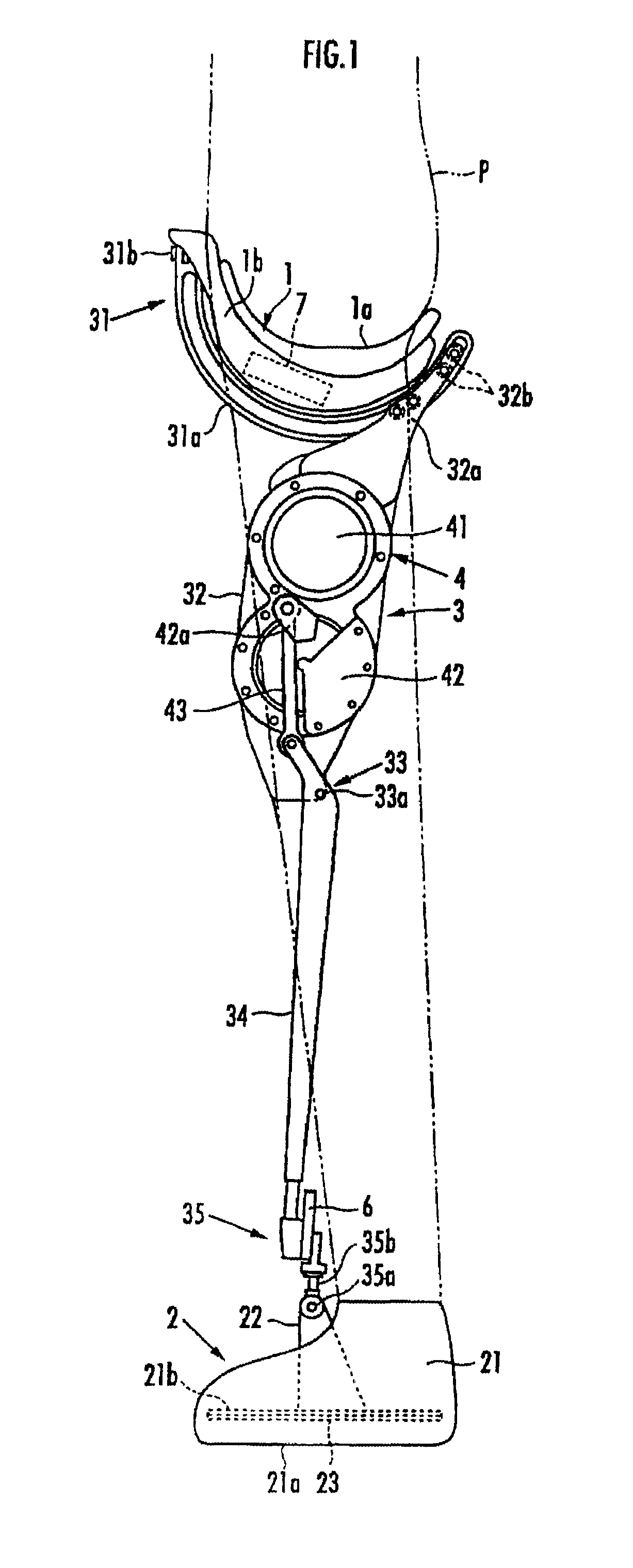
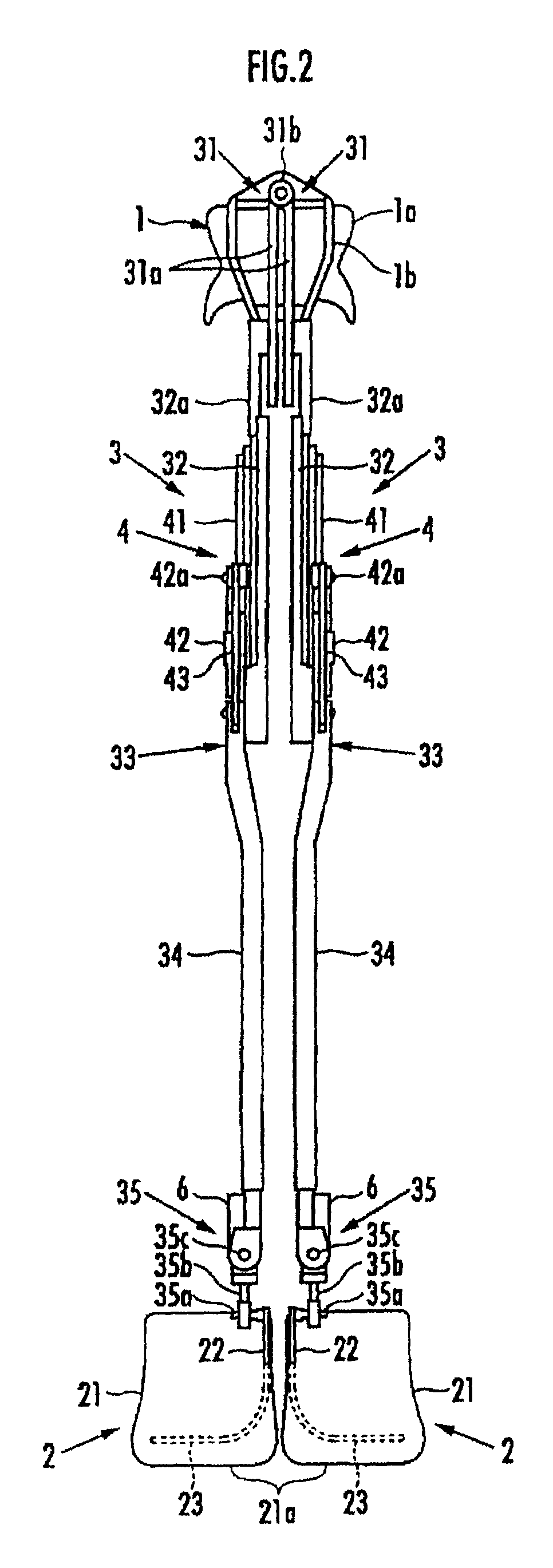
[0013]The following will describe a walking assistance device according to an embodiment of the present invention. As illustrated in FIG. 1 and FIG. 2, the walking assistance device has a seating member 1 serving as a load transmitting assembly on which a user P sits astride, a pair of right and left foot-worn assemblies 2 and 2 to be attached to the right and left feet of the user, and a pair of right and left leg links 3 and 3 provided between the seating member 1 and the right and left foot-worn assemblies 2 and 2.

[0014]Each of the leg links 3 is formed of a bendable link constituted of a first link member 32, which is connected to the seating member 1 through a first joint 31 at an upper end such that the first link member 32 is longitudinally swingable, and a second link member 34, which is connected to a lower end of the first link member 32 through a rotary second joint 33. The foot-worn assembly 2 is connected to a lower end of the second link member 34 through a third joint...


PUM


Abstract

A walking assistance device has a load transmitting assembly, a foot-worn assembly, and a leg link provided between the load transmitting assembly and the foot-worn assembly. The foot-worn assembly has a ground contact member, on which a user's foot rests, and a connecting member which connects the ground contact member to a joint at a lower end of the leg link. The ground contact member is provided with tread force sensors and the foot-worn assembly permits detection of a tread force. The connecting member is formed so as to rise in a cantilever manner from one lateral side of the ground contact member. The tread force sensors are installed in at least one location adjacent to the heel of the user's foot and in at least two locations adjacent to toes of the user's foot, with the latter two locations being laterally spaced apart.

Description

TECHNICAL FIELD[0001]The present invention relates to a walking assistance device which reduces load acting on a leg or legs of a user thereby to assist walking of the user.BACKGROUND ART[0002]Hitherto, as this type of walking assistance device, there has been known one having a load transmitting assembly, a foot-worn assembly to be attached to a foot of a user, and a leg link provided between the load transmitting assembly and the foot-worn assembly (refer to, for example, Japanese Patent Application Laid-Open No. 2007-20909). According to this device, at least a part of the weight of a user is supported by the leg link through the intermediary of the load transmitting assembly to reduce load acting on a leg of the user, thereby assisting the walking.[0003]In the conventional example described above, the foot-worn assembly includes a shoe having a sole, which is a ground contact member on which a foot of the user is rested, and a connecting member, which connects the shoe to a join...

Claims


Application Information

Patent Timeline
Patent Type & Authority Patents(United States)
IPC IPC(8): A61F5/00
CPCA61H3/008A61H3/00A61B5/1038A61B5/1116A61H2201/1633A61H2201/5061A61H2201/1215A61H2201/1436A61H2201/163A61H2201/1642A61H2201/165A61H2201/1676
Inventor KUDOH, HIROSHIENDO, YOSUKEIKEUCHI, YASUSHI
Owner HONDA MOTOR CO LTD
Why Eureka
Try Eureka