Guide for guiding a moveable carriage of a printer in a print direction, and printer

a printer and moveable technology, applied in the direction of printing, spacing mechanisms, printing mechanisms, etc., can solve the problems of hindering the movement of the carriage along the guide, and the initial linear design of the rod cannot be secured

Inactive Publication Date: 2007-08-09
OCE TECH
View PDF2 Cites 0 Cited by
  • Summary
  • Abstract
  • Description
  • Claims
  • Application Information

AI Technical Summary

Benefits of technology

[0006] The contact between the guiding rod and the support frame may be such that each guiding rod contacts each part of the support frame defining the corresponding recess. In the guide according to an embodiment of the present invention both recesses are positioned and shaped in a predefined manner to optimize accommodation of the rods, or at least a part thereof, such that movement of the carriage along the rods can take place relatively unhindered, independent of the thermal state of both the guide and the carriage mounted thereon. The recesses preferably substantially extend in the print direction. Magnetically attracting the rods allows substantially unhindered displacement, and in particular expansion, of these rods during heat-up of the guide, as a result of which the linearity of both rods can be secured in an optimum manner.
[0007] Moreover, a direct physical contact between each rod and each corresponding recess is established by means of the magnet. Therefore, the recesses are preferably adapted to establish at least one line contact between each guiding rod and each part of the support frame defining the corresponding recess. Realizing one or more line contacts between the rods and the support frame commonly improves stable support of the rods, thereby further securing linear precision of the guiding rods, and thereby also improving the load capacity of the guiding rods. Preferably, the at least one line contact substantially extends along the length of the corresponding recess to optimize these latter effects. The number of line contacts between each guiding rod and each recess is dependent on the design of both the guiding rod and the recess. Commonly, the guiding rod is shaped substantially circularly in cross-section. In case of a tight-fit between the guiding rod and the recess, wherein the guiding rod could have a similar, though inverted shape in cross-section, the number of line contacts is considered to be infinite. However, preferably, each recess is defined by at least two surfaces of the support frame, said surfaces mutually enclosing an angle. More preferably, the surfaces of the support frame define in cross-section a substantially V-shaped recess or a truncated V-shaped recess. In this manner, commonly two line contacts will be present between each guiding rod and the corresponding recess.
[0008] In order to optimize the physical (line) contact between each guiding rod and the corresponding recess, each recess is preferably defined by a substantially smooth part of the support frame. Moreover, a relatively smooth (plain) surface of the support frame defining each recess will facilitate expansion of the rods due to thermal influences, which will be in favor of the linear precision of the guide according to the present invention.
[0011] Commonly, the support frame and the guiding rods are composed of substantially different materials. The guiding rods are commonly made of steel, while the support frame is often formed by an extrusion profile made of aluminium. Typically, in this embodiment, bolting the guiding rods to the support frame, and thereby literally fixating both components to each other, would be undesirable due to a considerable difference in heat expansion between both components. By applying the magnets, a freedom of bidirectional movement, in particular expansion, of the guiding rods can be secured. Therefore, expansion of the rods due to thermal influences will be permanently and substantially unhindered.

Problems solved by technology

However, due to thermal expansion of the bolted rods during use, the (initial) linear design of the rods cannot be secured.
Movement of the carriage along the guide is hindered as a result of the non-linear design.

Method used


Image

  • Guide for guiding a moveable carriage of a printer in a print direction, and printer
  • Guide for guiding a moveable carriage of a printer in a print direction, and printer
  • Guide for guiding a moveable carriage of a printer in a print direction, and printer

Examples


Embodiment Construction

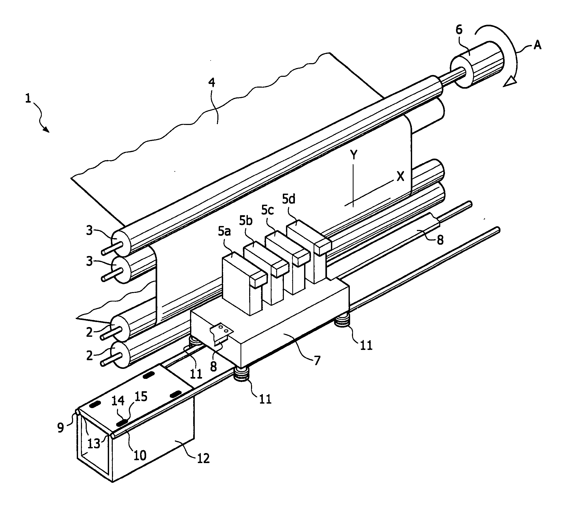
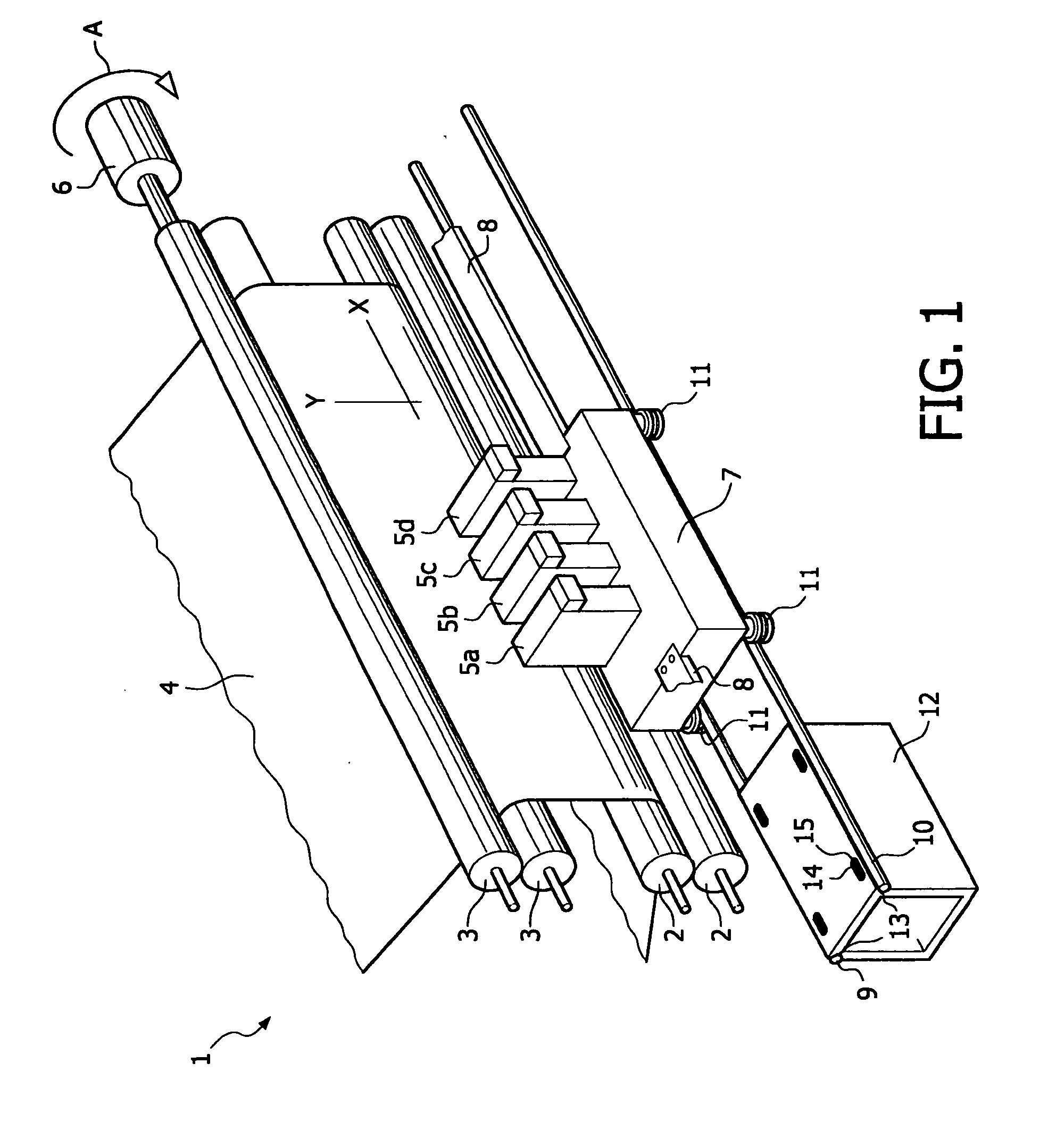
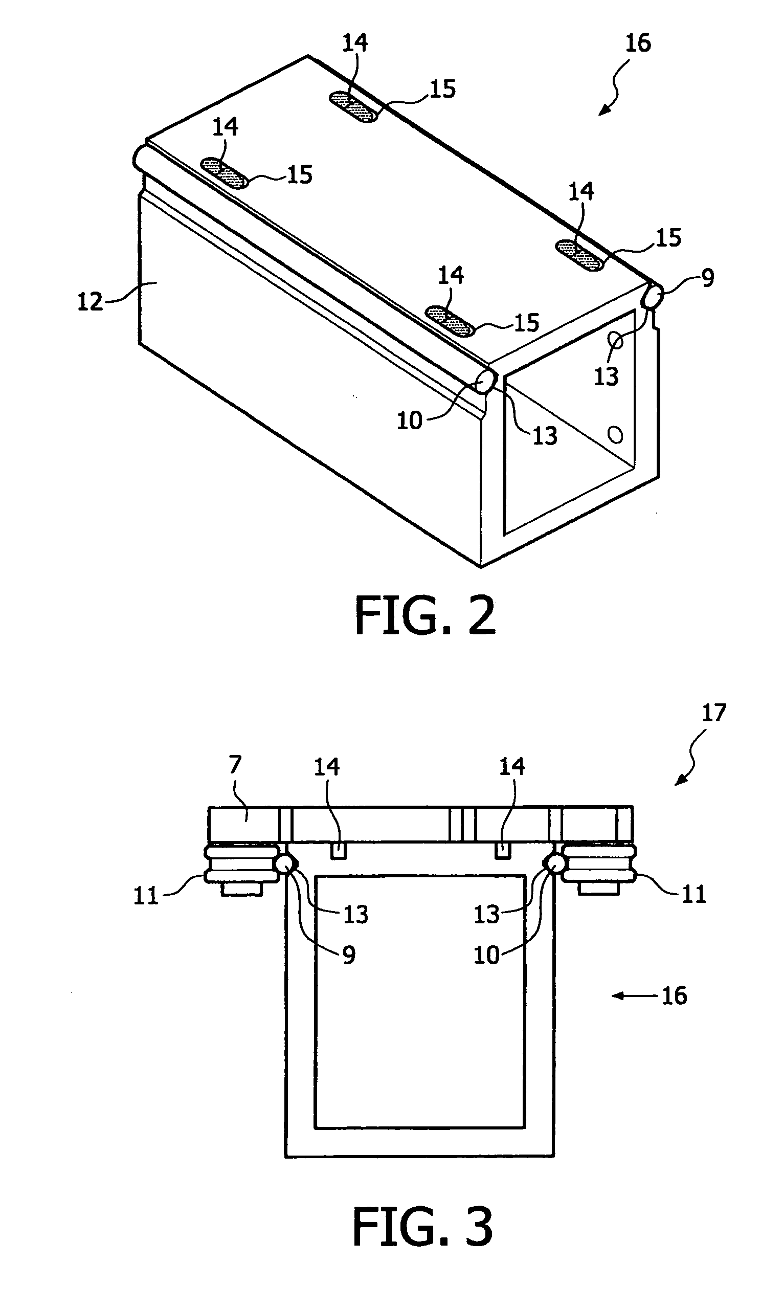
[0019] The present invention will now be described with reference to the accompanying drawings, wherein the same or similar elements will be identified with the same reference numerals. FIG. 1 is a perspective view of an inkjet printer 1. The printer 1 includes two pairs of rollers 2 and 3 for supporting a receiving material 4, for example a sheet of paper, and feeding it along four print heads 5a, 5b, 5c and 5d (each print head for one of the colors black, cyan, magenta and yellow). Roller pair 3 is drivable by means of motor 6. In this case the top one of the two rollers 3 is actively driven in a direction indicated by arrow A. As a result, the receiving material 4 can be displaced in the sub-scanning direction Y so that the receiving material 4 can be moved with respect to the print heads 5a, 5b, 5c, 5d. A scanning carriage 7 carries the four print heads 5a, 5b, 5c and 5d and can be reciprocated in the main scanning direction X, parallel to the roller pairs 2 and 3. For this purp...


PUM


Abstract

A guide for guiding a moveable carriage of a printer in a print direction includes a pair of spaced apart guiding rods. At least one support frame is provided with at least two elongated recesses, each of the recesses is adapted to accommodate at least a part of a guiding rod. A magnet magnetically attracts each guiding rod into a corresponding recess to establish physical contact between each guiding rod and the support frame.

Description

BACKGROUND OF THE INVENTION [0001] 1. Field of the Invention [0002] The present invention relates to a guide for guiding a moveable carriage of a printer in a print direction. The present invention further relates to a printer, including a carriage and a guide for guiding the carriage in a print direction. [0003] 2. Description of Background Art [0004] Guides for guiding a moveable carriage of a printer are known in the background art. These guides allow the carriage to be moved bidirectionally along the guide in a print direction. Commonly, the known guide comprises a set of two substantially parallel smooth, spaced apart guide rods made of steel on which the carriage is mounted. The rods, in particular the extremities of the rods are bolted onto a support structure in a predetermined manner. Bolting the rods onto the guide is commonly considered to be advantageous, since this kind of attachment allows support of relatively heavy carriages. The design of both the carriage and the g...

Claims


Application Information

Patent Timeline
Patent Type & Authority Applications(United States)
IPC IPC(8): B41J23/00
CPCB41J19/20
Inventor NIKKEL, JONATHAN H.J.J.
Owner OCE TECH
Why Eureka
Try Eureka