Method and device of compensating scattering light signals generated by light interaction with particles or biological cells moving in fluid currents, such as in flow cytometry

a scattering light and signal technology, applied in the field of optical measurements of scattering lights, can solve the problems of poor total angular resolution and limited number of detector elements forming said devices

Inactive Publication Date: 2013-05-14
STRICTES SRL
View PDF13 Cites 2 Cited by
  • Summary
  • Abstract
  • Description
  • Claims
  • Application Information

AI Technical Summary

Problems solved by technology

Said patents describe dedicated photoelectric detector devices which, in order to compensate for the signal reduction described by Mie's law, are characterized by an area which increases proportionally to the scattering angle: thereby the number of detector elements forming said devices is limited and the total angular resolution is poor.

Method used


Image

  • Method and device of compensating scattering light signals generated by light interaction with particles or biological cells moving in fluid currents, such as in flow cytometry
  • Method and device of compensating scattering light signals generated by light interaction with particles or biological cells moving in fluid currents, such as in flow cytometry
  • Method and device of compensating scattering light signals generated by light interaction with particles or biological cells moving in fluid currents, such as in flow cytometry

Examples


Embodiment Construction

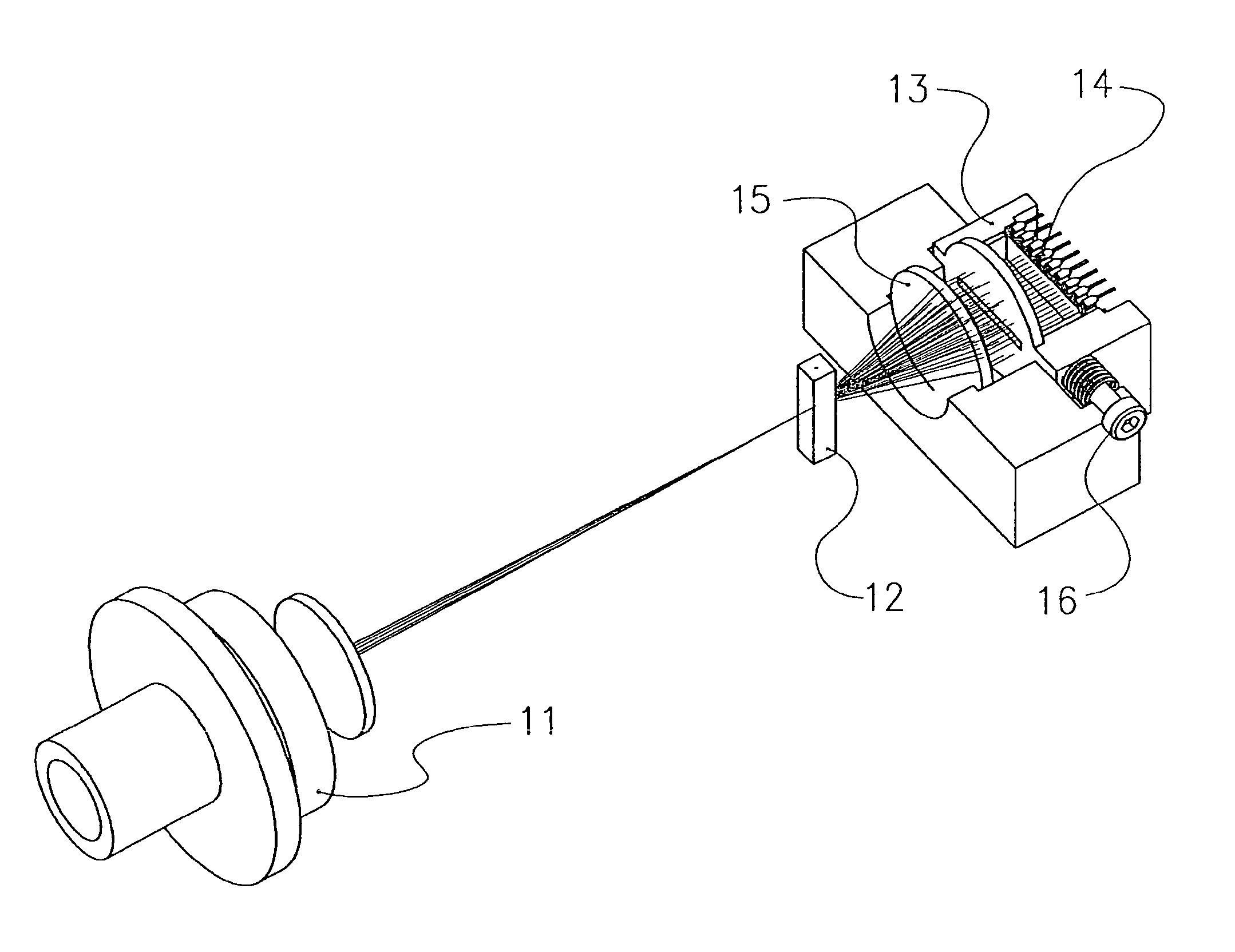
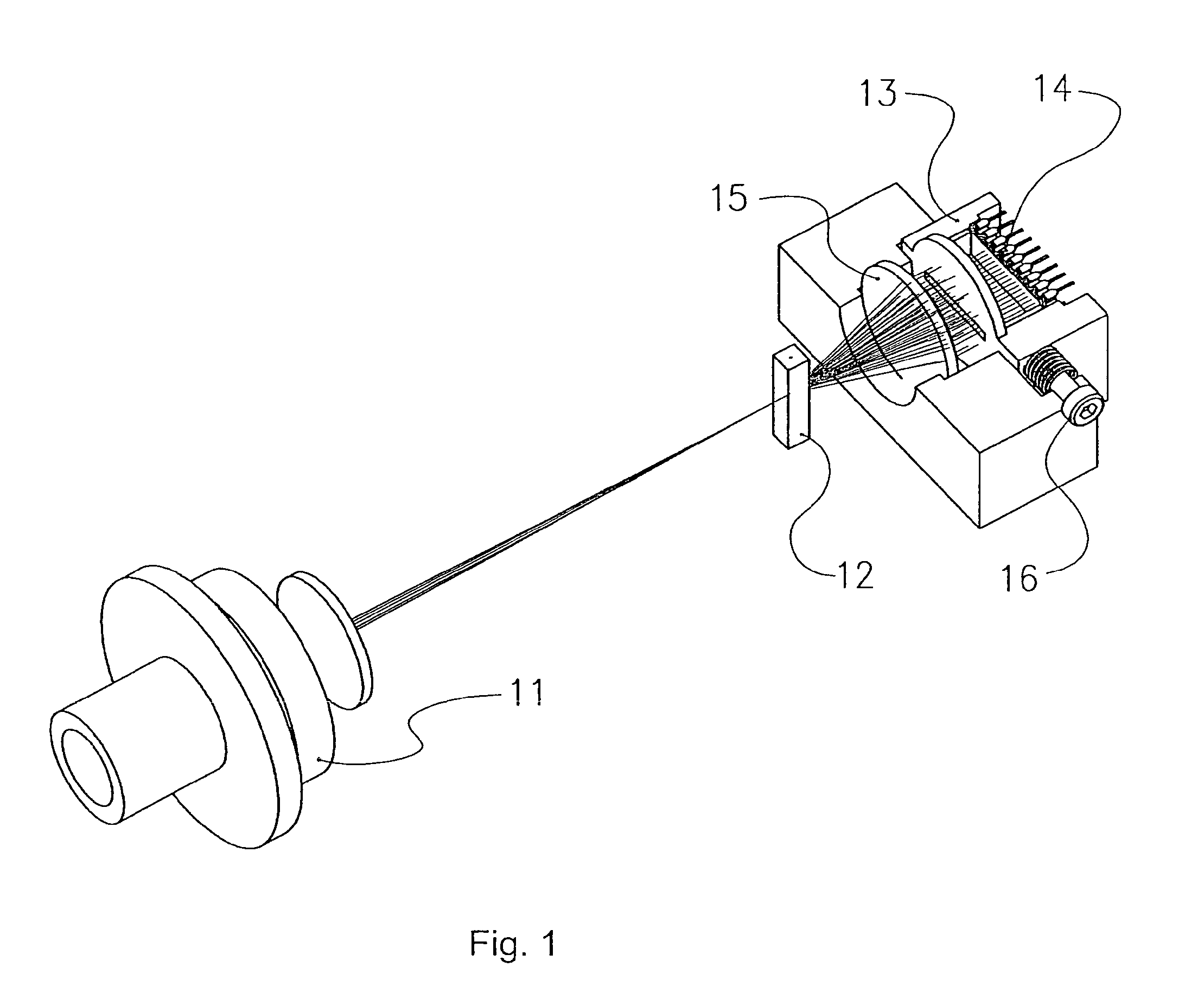
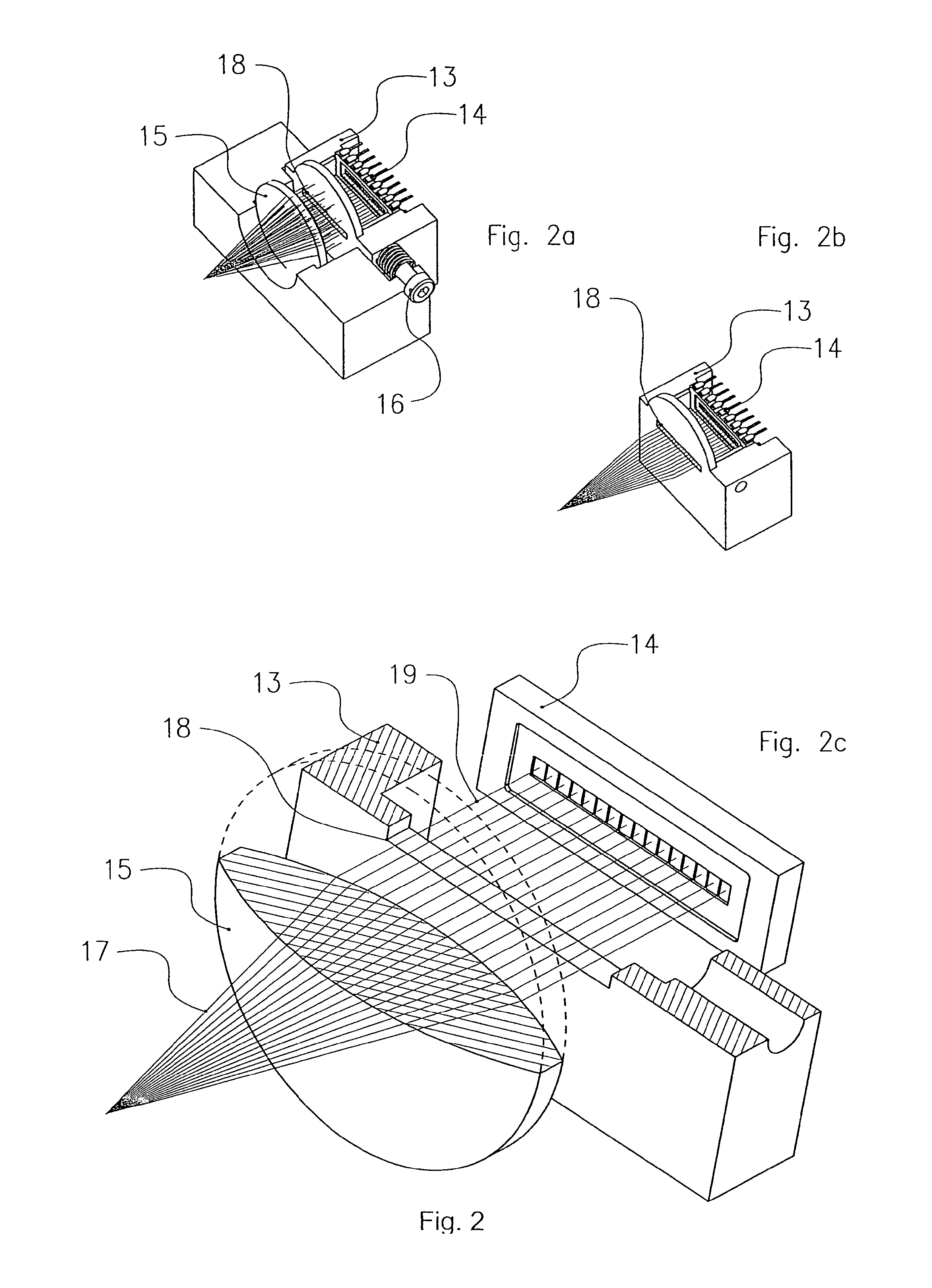
[0020]With reference to the accompanying FIG. 1, a perspective view of a preferred embodiment of the device according to the present invention is shown, in which the following component parts may be identified: a LED light source 11; a flow cell 12 (e.g. formed by means of a cell, model 151-051, made by Helma Italia Srl), a light collecting lens 15; a light detector 14 (e.g. formed by means of a CCD type detector), the supporting element 13 for said detector 14; means for adjusting the position of said supporting element 13, preferably comprising a position adjusting screw 16.

[0021]Said LED light source 11 comprises a light emitting element formed, for example, by means of a lamp, an individual or multiple LED, a laser diode or an ion laser device—adapted to emit a light beam and one or more lens forming the optical system to concentrate and focus said beam inside said flow cell 12, specifically on the particles carried by the conveying solution flow. Said light detector 14 preferab...


PUM

PropertyMeasurementUnit
sizeaaaaaaaaaa
diameteraaaaaaaaaa
anglesaaaaaaaaaa

Abstract

A method and device of detecting a scattering light beam for tools measuring scattering signals produced by the interaction of solid microparticles, such as a biological cells moving with a high-intensity, focused light beam, capable of reducing the influence of the cell movement with respect to the optical axis of the illuminating beam, and improving the quality of the signal characterized by the recognition of the individual particle or cell, specifically in fluid currents, such as those used in flow cytometry are disclosed.

Description

CROSS REFERENCE TO RELATED APPLICATIONS[0001]This application is a §371 of PCT / EP2009 / 055895, filed May 15, 2009, which claims priority from Italian Application No. FI2008A000095, filed May 15, 2008.FIELD OF THE INVENTION[0002]The present invention relates to the field of optical measurements on scattering lights used for recognizing even microscopic solid particles, such as for example blood cells, in biomedical apparatuses such as flow cytometers.STATE OF THE ART[0003]Detectors intended to provide information related to particle scattering according to certain dispersion angles are known. Some of these detectors of the prior art are protected by patents, among which U.S. Pat. No. 6,232,125 (Deka et al.) and U.S. Pat. No. 7,092,078 (Nagai et al.) are mentioned.[0004]Said patents describe dedicated photoelectric detector devices which, in order to compensate for the signal reduction described by Mie's law, are characterized by an area which increases proportionally to the scattering...

Claims


Application Information

Patent Timeline
Patent Type & Authority Patents(United States)
IPC IPC(8): G01N21/00
CPCG01N15/147G01N2015/1447G01N2015/1452
Inventor DALL'OGLIO, STEFANODALL'OGLIO, GIORGIO
Owner STRICTES SRL
Why Eureka
Try Eureka