Device for stripping sheathing on unbonded post-tensioning tendons

a technology of post-tensioning tendons and sheathing, which is applied in the direction of earthwork drilling, mining, metal working equipment, etc., can solve the problems of u-shaped design, impede clamping ability, and inability to fully spiral cut or remove excess sheathing, etc., to achieve convenient rotation of the device, strong blade configuration, and easy rotation

Active Publication Date: 2013-05-21
VIERECK KYLE +1
View PDF28 Cites 0 Cited by
  • Summary
  • Abstract
  • Description
  • Claims
  • Application Information

AI Technical Summary

Benefits of technology

[0015]Upon the blade reaching the bottom of the stressing anchor wedge pocket, the blade cuts the sheathing flush with the bottom of the stressing anchor wedge pocket in a single rotation, and the spiral waste sheathing easily falls away. Alternatively, the device may include handles or wrench flats to easily rotate the device around a tendon or may include a body of the same diameter as the cutting head. Alternatively, the device may include a “stop” attached to the cylindrical cutting head that prevents the blade from coming in direct contact with the bottom of the stressing anchor wedge pocket thereby dulling it prematurely.
[0016]One advantage of this device over previous spiral cut devices such as the '910 device and the '290 device is that a heavier, stronger blade configuration is used that does not require replacing as frequently. Another advantage is that entire length of the waste sheathing is cut, and the waste sheathing is automatically removed without the requirement of a separate waste sheathing removal step. One advantage of this device over the previous “plowing” devices such as the '088 device and the '996 device is that the helical engagement of the blade with the sheathing results in a clean cut of the waste sheathing flush with the bottom of the stressing anchor wedge pocket without the need for hammering. More advantages include the ease in accurately setting the device and that the entire length of the waste sheathing is cut and automatically removed without the requirement of a separate waste sheathing removal step. One advantage that this device has over all of the aforementioned devices is that the simplicity of the current device allows it to be produced in a more economical manner, and yet the device is more robust and less prone to breakdown or replacement.

Problems solved by technology

For maximum durability, the sheathing should cover the complete length of the tendon and not be too short; however, the sheathing cannot extend inside of the stressing anchor's wedge pocket because it would impede the clamping ability of the anchor wedges.
Unfortunately, the '910 device does not fully spiral cut or remove the excess sheathing, and as a result, the excess sheathing must be removed either by un-threading the sheathing off the tendon or by using a separate knife to slice the waste sheathing longitudinally before removing it from the tendon.
Additionally, the use of a stamped steel blade with this device would require frequent blade changes, and the U-shaped design complicates the hand rotation.
Unfortunately, as with the '910 device, the '290 device does not fully spiral cut or remove the excess sheathing, and as a result, the excess sheathing must be removed either by unthreading the sheathing off the tendon or by using a separate knife to slice the sheathing longitudinally before removing it.
Additionally, the blade used in this device dulls quickly and must be changed often, and the compressible tool body, combined with the U-shaped design, may make the device difficult to rotate by hand.
Unfortunately, the '088 device requires hammering to become fully engaged, and if the device is not fully engaged, sheathing will remain in the area to be occupied by the anchor wedges causing a sub-optimal locking of the tendon.
Unfortunately, the '996 device requires hammering to become fully engaged, and if the device is not fully engaged, the sheathing will not be fully cut.
This result makes removing the sheathing difficult and causes sub-optimal locking of the tendon in the area to be occupied by the anchor wedges.
Finally, the U-channel design may make the device difficult to rotate by hand.

Method used


Image

  • Device for stripping sheathing on unbonded post-tensioning tendons
  • Device for stripping sheathing on unbonded post-tensioning tendons
  • Device for stripping sheathing on unbonded post-tensioning tendons

Examples


Embodiment Construction

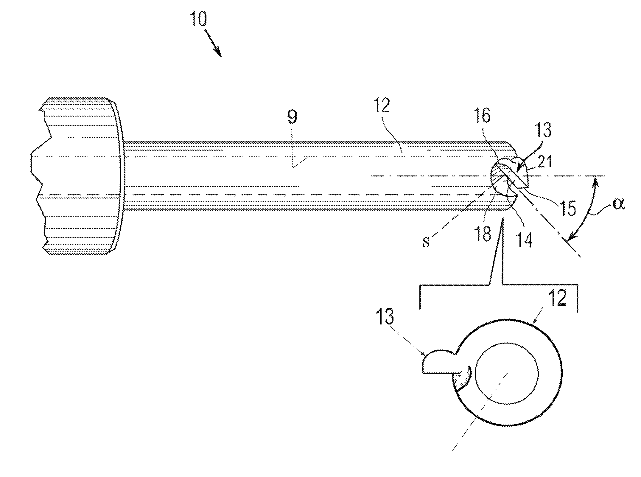
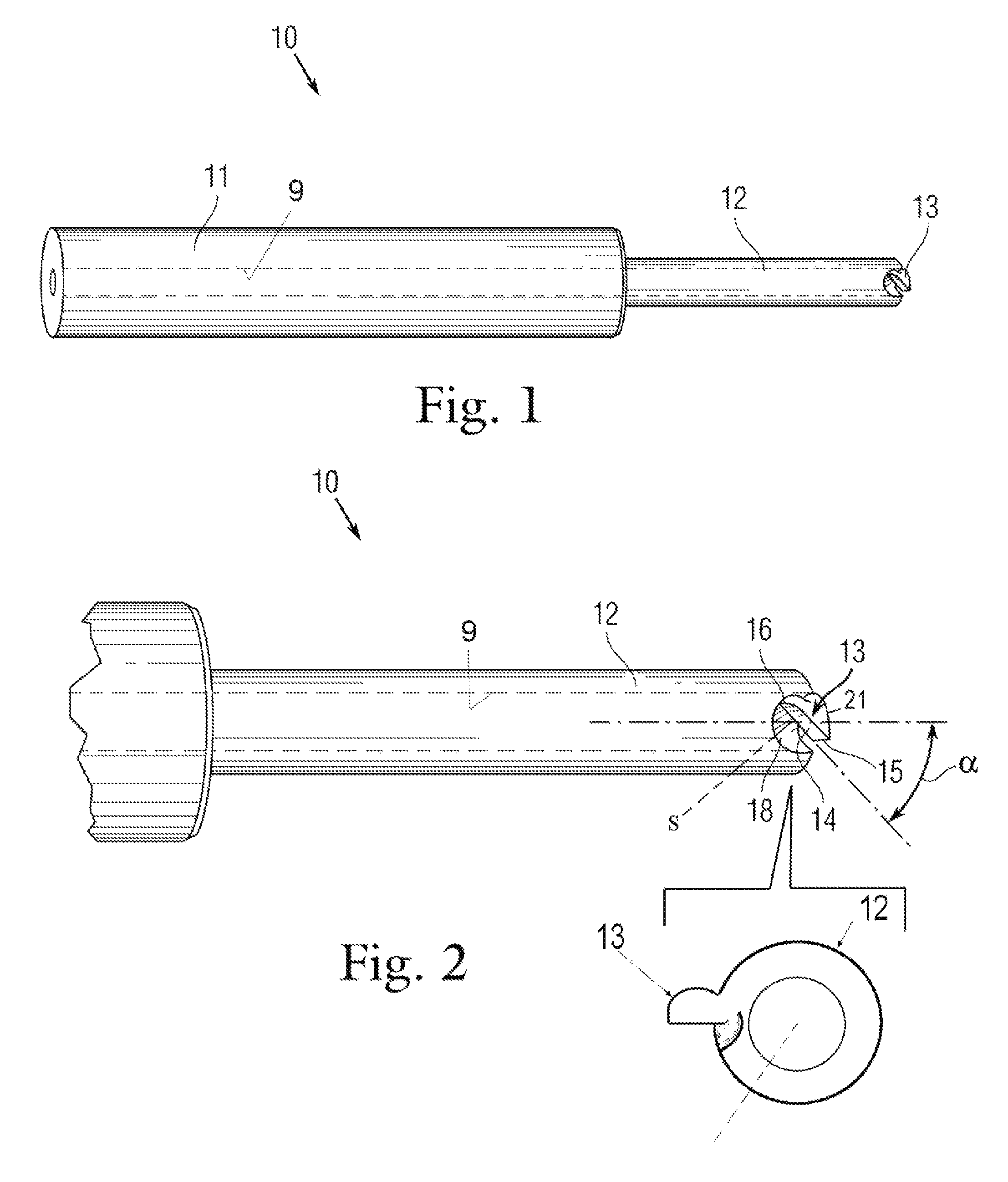
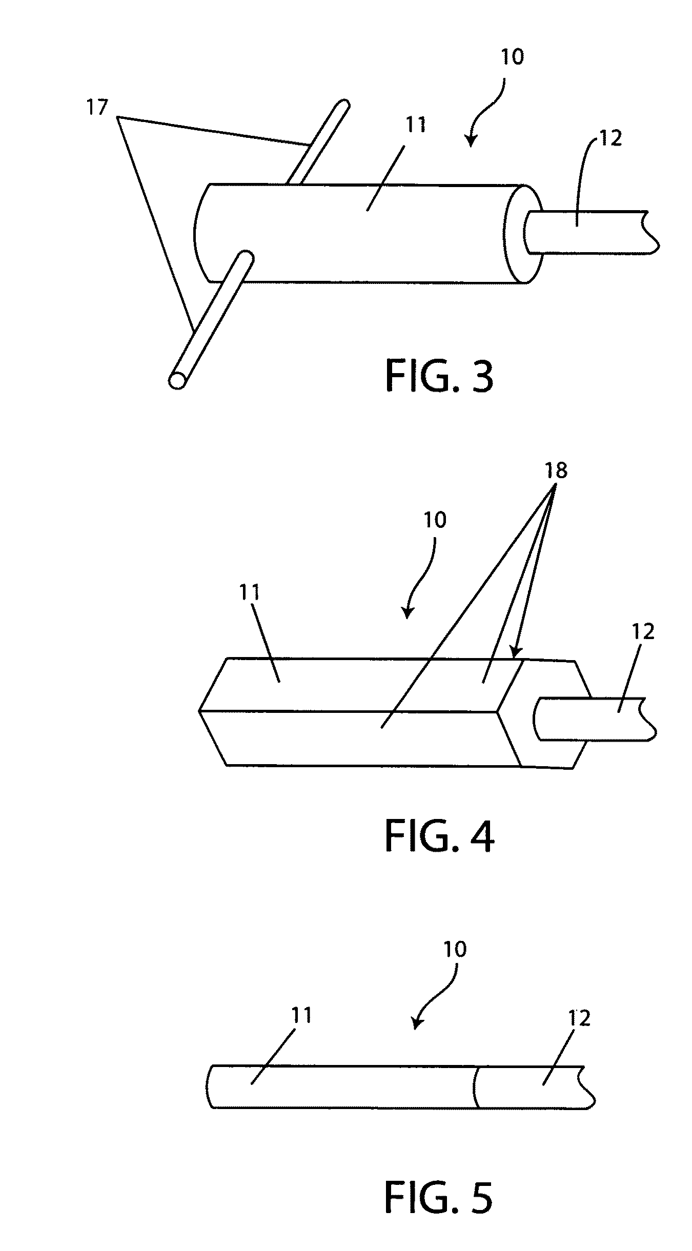
[0025]The present invention is a device for cutting and removing sheathing from a sheathed tendon during the post-tensioning process. In an embodiment, the device comprises a tubular body of uniform diameter attached to a tubular cutting head. The cutting head has a smaller diameter and is concentric with the tubular body. The cutting head is sized to fit within the wedge pocket of an anchor collar or “stressing anchor.” The body and cutting head have a through bore along their common longitudinal axis. The cutting head has a blade protruding radially from the distal edge, the blade having a planar cutting face radially offset from the tendon and angled at a pitch angle between 45 and 85 degrees from the longitudinal axis of the body. In use, the device is slipped over the stressing tail of the tendon until the cutting head engages with the sheathing to be cut. As the body is rotated causing the cutting head to turn about the tendon, the blade cuts a helical path through the entire ...


PUM

PropertyMeasurementUnit
pitch angleaaaaaaaaaa
transverse angleaaaaaaaaaa

Abstract

A device for helically cutting and automatically removing waste sheathing from the stressing tails of unbonded tendons. The device comprises an elongated body and an attached cutting head. Both the body and the cutting head have a uniform through bore along their longitudinal axis for accepting a post-tensioned tendon. The cutting head comprises an integral blade having a cutting face radially offset from the longitudinal axis and inclined at a pitch angle of between 45 and 85 degrees relative to the longitudinal axis. The blade cuts the sheathing while also ejecting the waste sheathing.

Description

CROSS-REFERENCE TO RELATED APPLICATIONS[0001]The present application derives priority from U.S. Provisional Patent Application No. 61 / 191,455 filed on Sep. 9, 2008, which is incorporated herein by reference.BACKGROUND OF THE INVENTION[0002]1. Field of the Invention[0003]The present invention relates generally to a post-tensioning tendon sheathing stripper for use in concrete structures utilizing unbonded post-tensioning systems and, more specifically, to a device for removing the plastic sheathing from the stressing end of tendons.[0004]2. Description of the Background[0005]Post-tensioning concrete entails the use of high-strength steel strand, “tendons,” that are embedded in concrete and tensioned after the concrete hardens. Using tendons under tension creates cast-in-place and precast concrete members that have superior strength characteristics when compared to similarly sized non-prestressed members. In unbonded post-tensioning applications, the steel tendons are first encased in...

Claims


Application Information

Patent Timeline
Patent Type & Authority Patents(United States)
IPC IPC(8): B21F13/00B26B27/00
CPCB26B27/00E21D20/00B26D3/11Y10T83/02
Inventor VIERECK, KYLEPRICE, RUSSELL L.
Owner VIERECK KYLE
Why Eureka
Try Eureka