
Retainer structure

a technology of a container and a handle is applied in the field of container structures, which can solve problems such as bad workability, and achieve the effect of improving the workability of attaching and removing

Active Publication Date: 2013-05-21
NIFCO INC
View PDF20 Cites 40 Cited by
  • Summary
  • Abstract
  • Description
  • Claims
  • Application Information

AI Technical Summary

Benefits of technology

The retainer structure enhances workability by enabling attachment with only insertion and removal through rotation and movement, improving ease and efficiency of attaching and removing components from panels without requiring complex operations.

Problems solved by technology

However, in the structure of the Patent Document 1, when the component is attached to the panel, or removed from the panel, it is required that the retainer clip is engaged with the component, or removed from the component by coming around a back face side of the panel, to cause bad workability.

Method used


Image

  • Retainer structure
  • Retainer structure
  • Retainer structure

Examples


Embodiment Construction

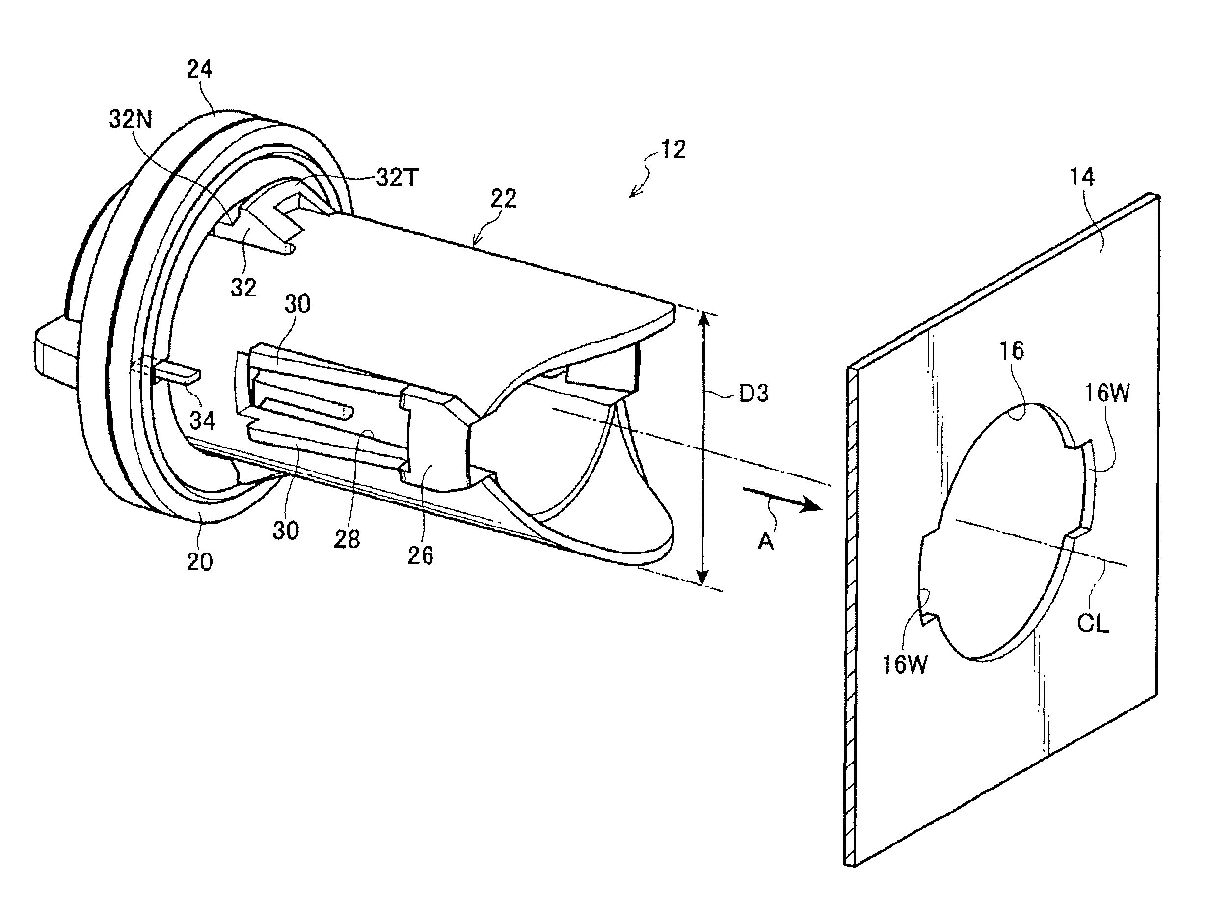
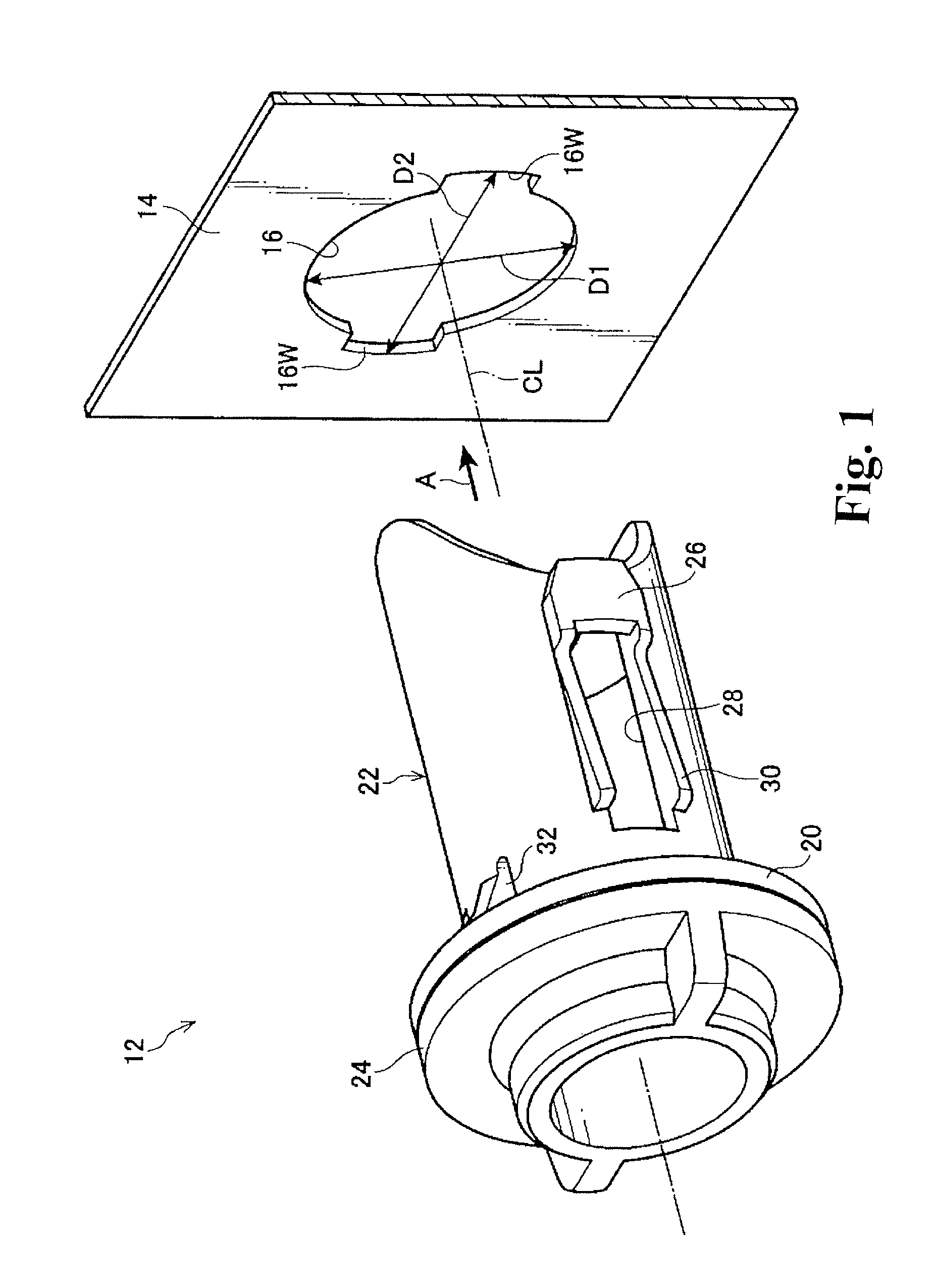
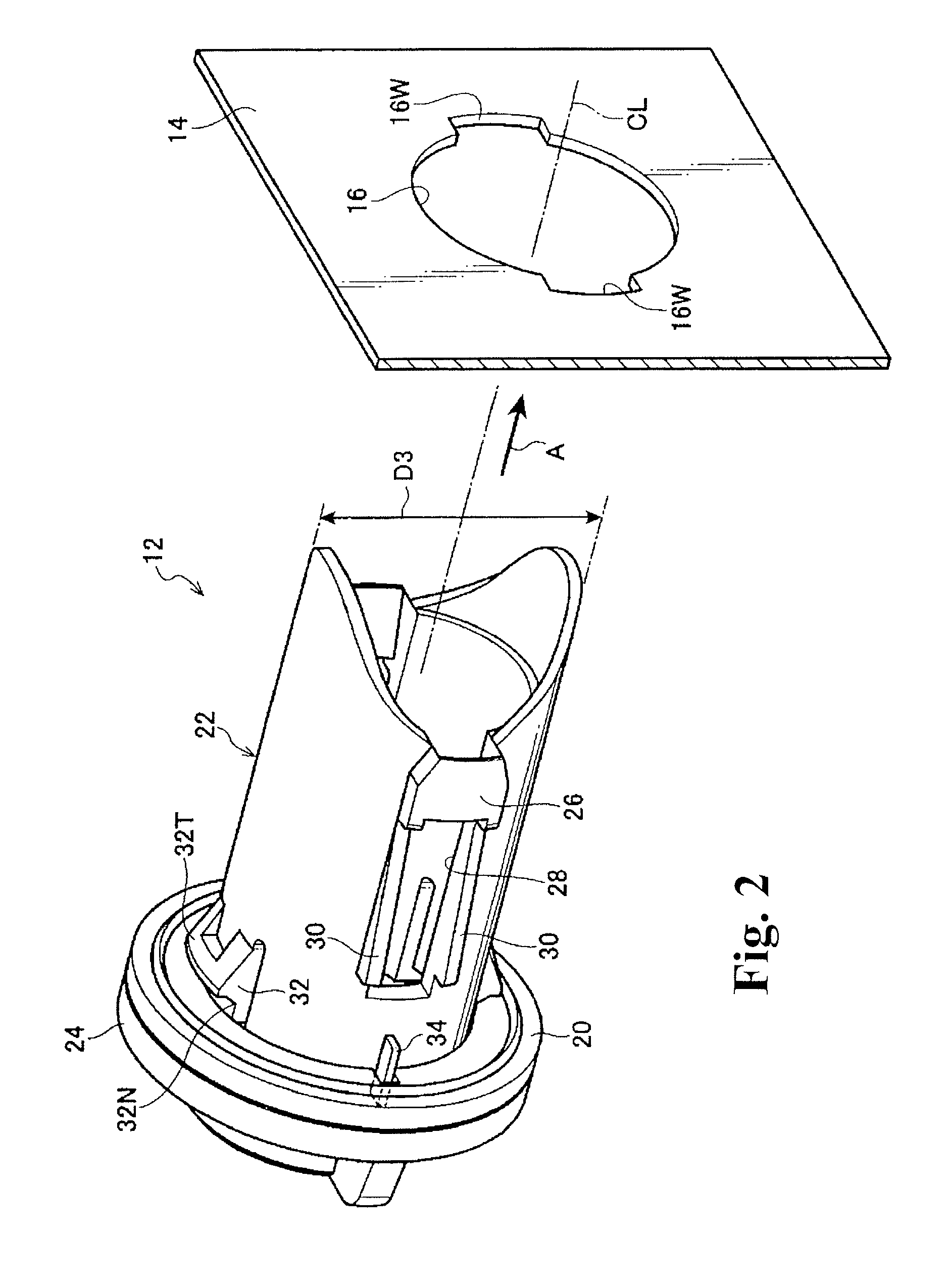
[0033]FIGS. 1 and 2 show a retainer structure 12 of one embodiment of the present invention. Also, FIGS. 3 to 5 show a state in which a cap 18 is attached to a body panel 14 near a fuel lid of an automobile by using the retainer structure 12. In the body panel 14 of the automobile, an attachment hole 16 is formed. When a retainer main body 22 is inserted and fixed in the attachment hole 16, and also the cap 18 is attached to the body panel 14 through the retainer main body 22, the retainer structure 12 of the present embodiment is applied. Incidentally, in the drawings, an insertion direction of the retainer main body 22 is shown by an arrow A.

[0034]The attachment hole 16 is formed in an approximately circular shape including a certain amount of an inner diameter D1. Also, in the attachment hole 16, expanded-diameter portions 16W wherein the diameter is partially expanded are formed in one portion or a plurality of portions (two portions in a crosswise direction symmetric relative t...


PUM


Abstract

A retainer structure having excellent workability of attaching to and removing from a panel is obtained. In an approximately cylindrical retainer main body (22), a cap holding portion (26) for attaching a cap (18) which is an attached member, and a panel clamping piece (32) contacting a body panel (14) from a side opposite to a seal packing (20) so as to clamp the body panel (14) between the panel clamping piece and a flange portion (24), are formed. The cap holding portion (26) and the panel clamping piece (32) are formed at positions different in a circumferential direction of the retainer main body (22).

Description

RELATED APPLICATIONS[0001]The present application is National Phase of International Application No. PCT / JP2010 / 059560 filed Jun. 4, 2010, and claims priority from Japanese Application No. 2009-135445, filed Jun. 4, 2009.TECHNICAL FIELD[0002]The present invention relates to a retainer structure, more specifically, the retainer structure for holding an attached member in a state inserted into an attachment hole of a vehicle-body panel.BACKGROUND ART[0003]As a structure for attaching a component (the attached member) relative to a panel, in Patent Document 1, there is shown a structure in which a jaw portion of the component is inserted to pass through the attachment hole of the panel, and a retainer clip is engaged with the jaw portion of a protruding small-diameter portion so as to attach by clamping the panel with an expanding width portion.[0004]However, in the structure of the Patent Document 1, when the component is attached to the panel, or removed from the panel, it is require...

Claims


Application Information

Patent Timeline
Patent Type & Authority Patents(United States)
IPC IPC(8): E05B65/12B60K15/05E05B79/04E05B83/34F16B19/00F16B21/04
CPCB60K15/05F16B21/04F16B19/1081B60K2015/0561F16B9/023Y10T403/4662Y10T403/4665Y10T24/45508F16B2200/20F16B2200/30F16B9/056
Inventor TAKAHASHI, SHIGERUISHIKAWA, YOSHIKI
Owner NIFCO INC
Learn More