
Device for controlling a computer-based pointer in a system comprising various types of displays

a computer-based pointer and display technology, applied in computing, instruments, electric digital data processing, etc., can solve the problems of not being able to ensure the operation of the ccd whose electronics and computing is used, and not benefiting from the same level of computer security as the “avionics world,

Active Publication Date: 2013-05-28
THALES SA
View PDF7 Cites 0 Cited by
  • Summary
  • Abstract
  • Description
  • Claims
  • Application Information

AI Technical Summary

Benefits of technology

The patent is about a solution to the problem of someone accidentally or intentionally diverting the pilot's attention from critical tasks by using "open world" applications in a civilian cockpit. One particular issue is the appearance of two cursor movements, which can be caused by malicious or incorrect operation of these applications. The proposed solution involves disabling the open world application when the cursor is in the avionics world, so that it cannot display consistent cursor movements based on the real movements of the CCD. This ensures that the pilot's attention is always directed towards the most important tasks.

Problems solved by technology

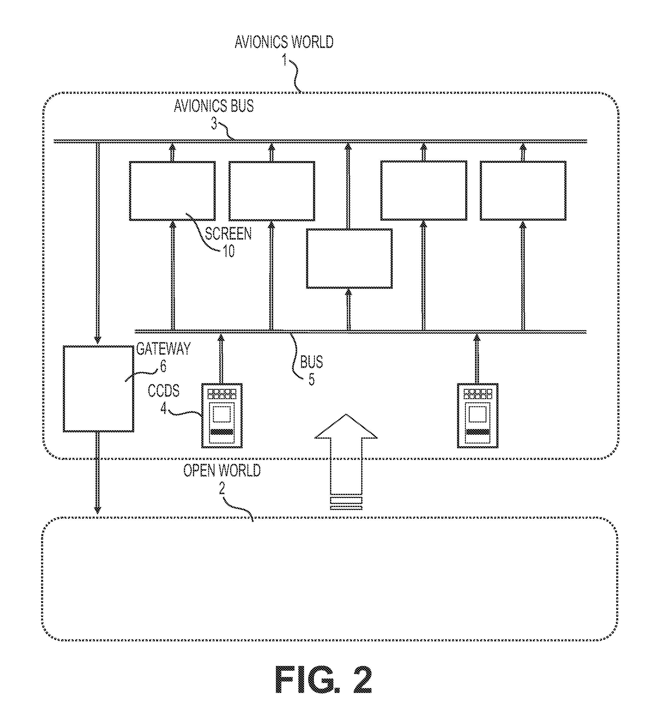
However, this “open world” does not benefit from the same level of computer security as the “avionics world”.
If no precautions are taken, it is therefore liable to disrupt or disturb the operation of the “avionics world” through the common control of the “CCDs”.
It may not be ensured by the CCD whose electronics and computing are necessarily rudimentary.
These things would all be impossible if the CCD worked in absolute coordinates.
This implementation exhibits a major drawback: the latency of the pointer for the open world is much more significant than the latency of the pointer for the avionics world, and more significant than the maximum latency of 100 milliseconds authorized by the “A661” reference aeronautical standard.

Method used


Image

  • Device for controlling a computer-based pointer in a system comprising various types of displays
  • Device for controlling a computer-based pointer in a system comprising various types of displays
  • Device for controlling a computer-based pointer in a system comprising various types of displays

Examples


Embodiment Construction

[0046]In what follows, the system described is more specifically a flight management system. But, of course, the invention can be applied without particular difficulties to any computer-based system comprising secure and non-secure display means.

[0047]FIG. 3 represents the two operating modes of a CCD according to the invention. On the left view, the CCD sends the pointer control instructions to the avionics world. In this figure and on the following one, the following conventions have been adopted:[0048]the instructions or the data provided by the CCD to the “CCD manager” are denoted ICCD→M,[0049]the instructions or the data provided by the CCD to the “open world” are denoted ICCD→MO,[0050]the instructions or the data provided by the “CCD manager” to the CCD are denoted IM→CCD,[0051]the instructions or the data provided by the “CCD manager” to the “avionics world” are denoted IM→MA.

[0052]The displacement instructions ICCD→M are provided to the avionics system by way of a management...


PUM


Abstract

The general field of the invention is that of devices for controlling a computer-based pointer of a computer-based assembly comprising two different computer-based systems, a first secure system comprising at least one first viewing screen and a man-machine interface called CCD controlling the position of the pointer, and a second non-secure system comprising at least one second viewing screen controlled by the same CCD. The control device according to the invention comprises a means called the “CCD manager” belonging to the first system, ensuring the control of the CCD transmission links and comprising the following functions activated when a displacement instruction is transmitted by the user to the CCD, the pointer occupying a first position in the reference plane, determination of the new position of the pointer, determination of the pointer membership area as a function of this new position, authorization of transfer of the displacement instructions coming from the CCD to the secure system or to the open system corresponding to the previously determined membership area.

Description

CROSS-REFERENCE TO RELATED APPLICATIONS[0001]This application is a National Stage of International Patent Application No. PCT / EP2008 / 066312, filed on Nov. 27, 2008, which claims priority to foreign Patent Application No. FR 07 / 08393, filed on Nov. 30, 2007, the disclosures of which are incorporated herein by reference in their entirety.FIELD OF THE INVENTION[0002]The field of the invention is that of systems comprising command or control facilities possessing a significant assembly of viewing devices having to display a large amount of information, some of which is vital for the operation or security of the system. The favored field of application is aeronautics, due to the fact that the instrument panels of modern aircraft possess several viewing screens making it possible to display, to control or to modify the information necessary for piloting and navigation. In a general manner, hereinafter in the text, the whole assembly of the secure onboard management system necessary for pi...

Claims


Application Information

Patent Timeline
Patent Type & Authority Patents(United States)
IPC IPC(8): G09G5/00G06F3/048G06F3/0481
CPCG06F3/0481G09G5/08G06F2203/04803G09G2310/04
Inventor LEFORT, MARCAYMERIC, BRUNOBONNET, DENIS
Owner THALES SA
Learn More