Valve gear of an internal combustion engine

Active Publication Date: 2005-05-05
MITSUBISHI JIDOSHI ENG +1
View PDF2 Cites 1 Cited by
  • Summary
  • Abstract
  • Description
  • Claims
  • Application Information

AI Technical Summary

Benefits of technology

[0012] An object of the present invention is to provide a valve gear of an internal combustion engine, which is capable of promptly switching the position of a piston in a rocker arm t

Problems solved by technology

In a low rotation region of the engine, the rotation speed of the oil pump is low and hence an adequate amount of discharge cannot be expected.
This poses a problem that the engine operating condition cannot be switched prompt

Method used


Image

  • Valve gear of an internal combustion engine
  • Valve gear of an internal combustion engine
  • Valve gear of an internal combustion engine

Examples


first embodiment

[0028] A valve gear with a cylinder suspending mechanism of an engine according to the present invention will be described below.

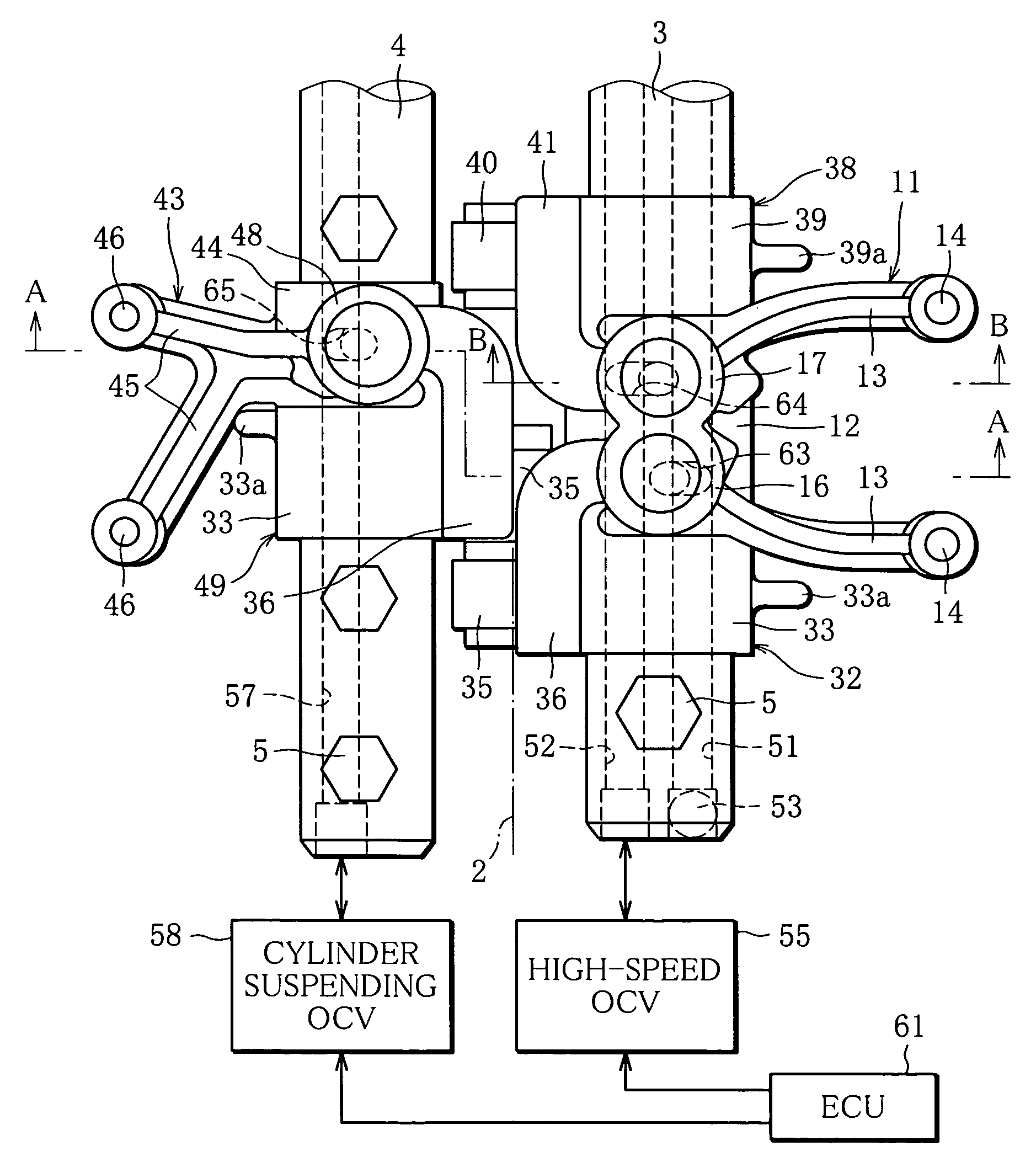
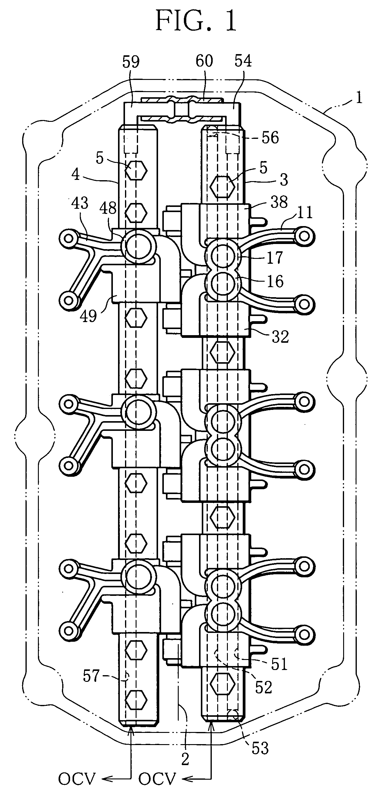
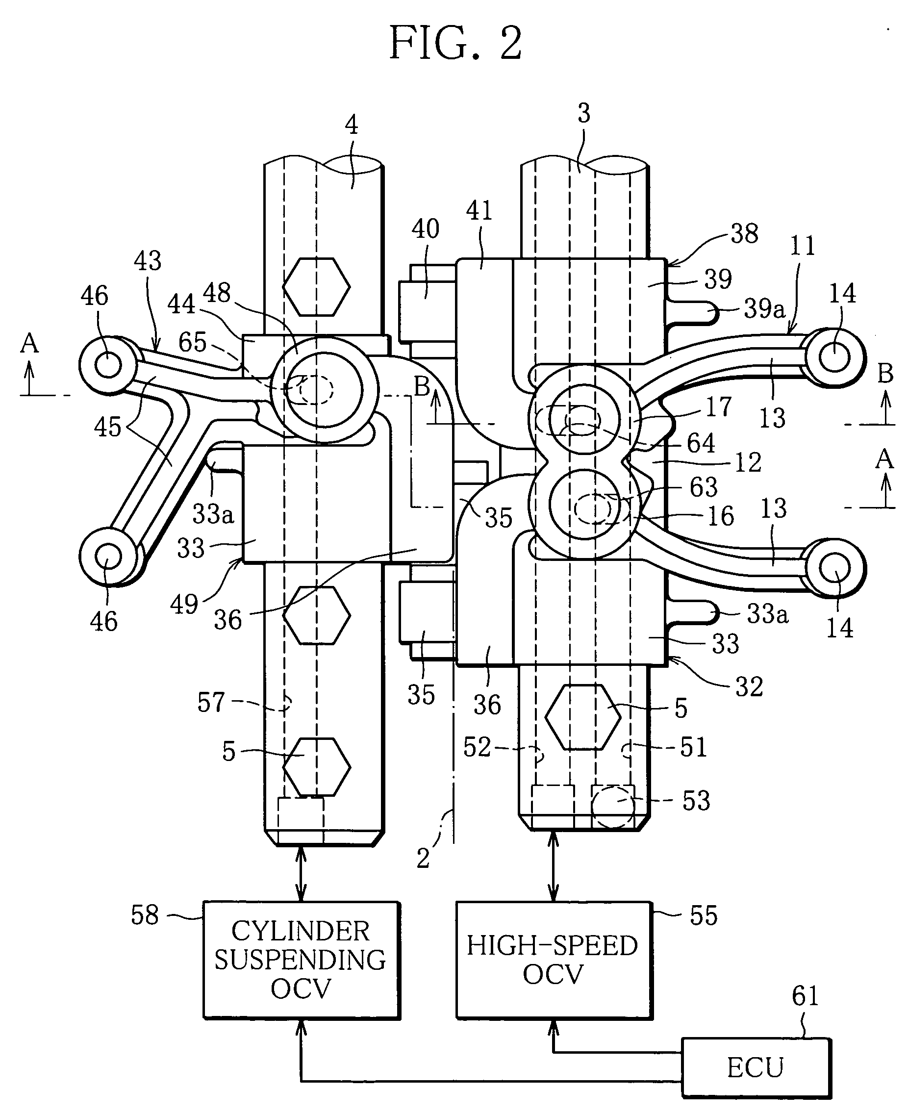
[0029] The engine according to the present embodiment is constructed as a V-six cylinder gasoline engine having four valves per cylinder, and is designed to be capable of switching a high-speed mode for realizing particularly high engine output, a low-speed mode for dealing with normal engine output, and a cylinder suspending mode for suspending cylinders located on one of two banks. To this end, valve gears of both banks each have a switching mechanism for switching the low-speed mode and the high-speed mode, and one of the banks is provided with a cylinder suspending mechanism. First of all, an explanation will be provided about a configuration of the bank having the cylinder suspending mechanism (hereinafter referred to as a suspension cylinder bank, and the opposite one as a non-suspension cylinder bank).

[0030] Suspension Cylinder Bank

[0031]FIGS. 1 t...

second embodiment

[0104] Next, a second embodiment will be explained, in which this invention is embodied in a different valve gear of an engine.

[0105] The valve gear of this embodiment has a construction in which the cylinder suspending mechanism is removed from the valve gear of the first embodiment. In other words, it only comprises a switching mechanism for switching the low-speed mode and the high-speed mode. In the following, differences between this embodiment and the first embodiment will be mainly described based on the configuration of the suspension cylinder bank according to the first embodiment. Common parts denoted by like numerals will be briefly explained.

[0106]FIG. 9 is an enlarged partial plan view showing details of the valve gear for one cylinder, FIG. 10 is an enlarged partial plan view showing the positional relation of drive rocker arms and driven rocker arms with respect to the cams, and FIG. 11 is a cross-sectional view taken along line D-D of FIG. 9 showing a state where th...


PUM


Abstract

A valve gear for an internal combustion engine capable of promptly switching the position of a piston in a rocker arm to thereby change the engine operating condition with a satisfactory response, even in a low rotation region in which an adequate amount of oil discharged from an oil pump cannot be expected. Depending on positions of pistons slidably fitted in low-speed and high-speed cylinder portions provided in an intake driven rocker arm, a low-speed or high-speed drive rocker arm is selectively operated to press a corresponding one of the pistons. The piston in the low-speed cylinder portion switched in a low rotation region is made smaller in diameter than the piston in the high-speed cylinder portion, to be enabled to be promptly switched.

Description

CROSS-REFERENCE TO RELATED APPLICATIONS [0001] This Nonprovisional application claims priority under 35 U.S.C. §119(a) on Patent Application Nos. 2003-326793 and 2003-326794 both filed in Japan on Sep. 18, 2003, the entire contents of which are hereby incorporated by reference.BACKGROUND OF THE INVENTION [0002] 1. Field of the Invention [0003] The present invention relates to a valve gear of an internal combustion engine (hereinafter referred to as engine). [0004] 2. Description of the Related Art [0005] To realize engine-output characteristics optimum for operating regions, there have been proposed a variety of engines adapted to switch valve-opening periods and lift amounts of intake and exhaust valves, etc. (refer to Japanese provisional patent publication no. 2001-41017, for example). [0006] The engine disclosed in this publication is provided with a driven rocker arm supported by a rocker shaft so as to be rocked by a first cam for low speed to thereby drive the intake valve to...

Claims


Application Information

Patent Timeline
IPC IPC(8): F01L1/18F01L1/26F01L1/34F01L13/00
CPCF01L1/181F01L1/267Y10T74/2107F01L2101/00F01L2105/00F01L13/0036F01L2301/00F01L2305/00F01L13/00F01L1/18
Inventor TAKAYASU, NORIOOKA, TOSHIHIKONAGIRA, TETSUSHIANDO, SATOSHIMURATA, SHINICHITOKUHISA, MASANORI
Owner MITSUBISHI JIDOSHI ENG
Why Eureka
Try Eureka