Method of transmitting scheduling reference signal

a technology of a scheduling reference signal, applied in the field of radio communication, can solve problems such as interfering between scheduling reference signals transmitted by respective ues, achieve efficient uplink scheduling, reduce interfering between scheduling reference signals of respective user equipments, and obtain uplink channel information more accurately

Inactive Publication Date: 2013-05-28
LG ELECTRONICS INC
View PDF13 Cites 20 Cited by
  • Summary
  • Abstract
  • Description
  • Claims
  • Application Information

AI Technical Summary

Benefits of technology

[0012]Scheduling reference signals transmitted by a plurality of user equipments are multiplexed in frequency domain, time domain or code domain by keeping orthogonality between the scheduling reference signals. Interference between scheduling reference signals of respective user equipments can be reduced. A base station can obtain uplink channel information more accurately, thereby enabling efficient uplink scheduling.

Problems solved by technology

If a plurality of UEs transmits the scheduling reference signals over the entire frequency bands in a radio communication system with limited uplink frequency resources, interference occurs between the scheduling reference signals transmitted by the respective UEs.

Method used


Image

  • Method of transmitting scheduling reference signal
  • Method of transmitting scheduling reference signal
  • Method of transmitting scheduling reference signal

Examples


Embodiment Construction

[0026]The present invention will now be described in detail in connection with specific embodiments with reference to the accompanying drawings.

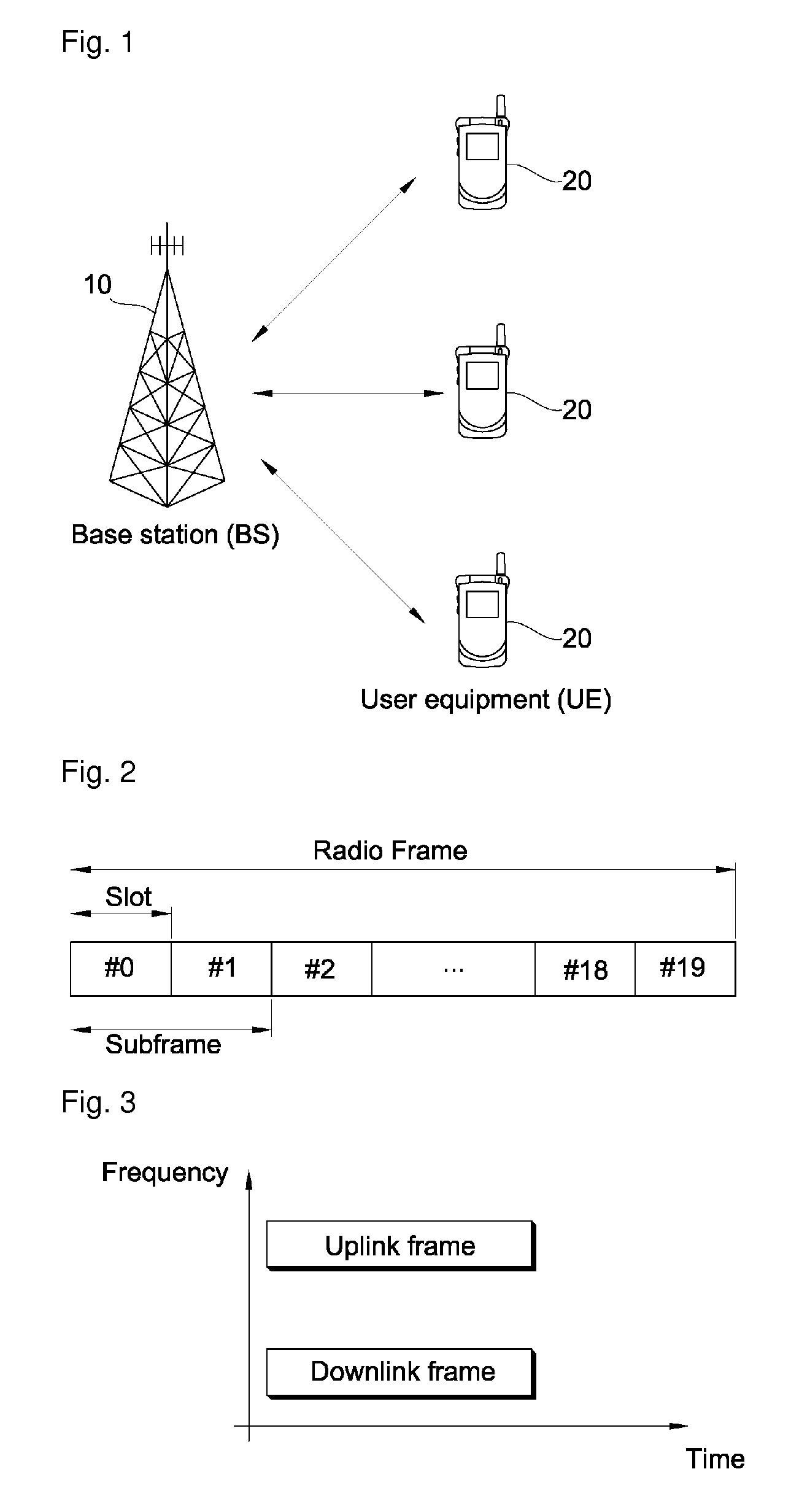
[0027]FIG. 1 is a block diagram of a radio communication system. The radio communication system is disposed over a wide area in order to provide various communication services such as voice and packet data.

[0028]Referring to FIG. 1, the radio communication system includes UEs 20 and a BS 10. The UE 20 may be fixed or have mobility and can also be called other terms such as a Mobile Station (MS), a User Terminal (UT), a Subscriber Station (SS) and a wireless device. The BS 10 generally refers to a fixed station communicating with the UE 20, and can also be called other terms such as Node-B, a Base Transceiver System (BTS) and an access point. One or more cells may exist in one BS 10

[0029]Hereinafter, the downlink refers to transmission from the BS 10 to the UE 20, and the uplink refers to transmission from the UE 20 to the BS 10. In the downl...


PUM


Abstract

A method of transmitting a scheduling reference signal (SRS) for uplink scheduling is provided. The method includes transmitting a SRS on a first partial SRS transmission band in a first transmitting time, and transmitting the SRS on a second partial SRS transmission band in a second transmitting time, wherein the first and the second partial SRS transmission bands are parts of a full SRS transmission band and have exclusive positions with each other in the full SRS transmission band, the full SRS transmission band selected for uplink scheduling, the full SRS transmission band comprising a plurality of partial SRS transmission bands.

Description

CROSS-REFERENCE TO RELATED APPLICATIONS[0001]This application is the National Stage filing under 35 U.S.C. §371 of International Application No. PCT / KR2008 / 000665, filed on Feb. 4, 2008, which claims the benefit of earlier filing date and right of priority to Korean Application No. 10-2007-0082117, filed on Aug. 16, 2007, and also claims the benefit of U.S. Provisional Application Ser. No. 60 / 888,056, filed on Feb. 2, 2007.TECHNICAL FIELD[0002]The present invention relates to radio communication, and more particularly, to a method of transmitting a scheduling reference signal, that is, a reference signal for uplink scheduling.BACKGROUND ART[0003]The next-generation mobile communication system must be able to transmit high quality and high capacity multimedia data at high speed using limited frequency resources. In order to enable it, inter-symbol interference and frequency selective fading, which occur at the time of high-speed transmission, must be overcome while maximizing frequen...

Claims


Application Information

Patent Timeline
Patent Type & Authority Patents(United States)
IPC IPC(8): H04W4/00H04B7/208
CPCH04L5/0053H04L5/0007H04L5/0016H04L5/0037H04W72/21
Inventor KIM, HAK SEONGYUN, YOUNG WOOKIM, KI JUNLEE, DAE WONYOON, SUK HYONAHN, JOON KUI
Owner LG ELECTRONICS INC
Why Eureka
Try Eureka