
Medical lead assembly and method for implantation thereof

a technology of medical lead and assembly, which is applied in the direction of internal electrodes, transvascular endocardial electrodes, therapy, etc., can solve the problems of lead fracture risk, lead stiffness decrease, and severe injuries, so as to reduce the degree of fracture, increase the stiffness, and the effect of different stiffness

Active Publication Date: 2013-05-28
ST JUDE MEDICAL
View PDF10 Cites 2 Cited by
  • Summary
  • Abstract
  • Description
  • Claims
  • Application Information

AI Technical Summary

Benefits of technology

[0010]A further object of the invention is to provide a method for implanting a medical implantable lead into a human or animal body wherein the flexibility can be regulated to a desired degree after implantation.
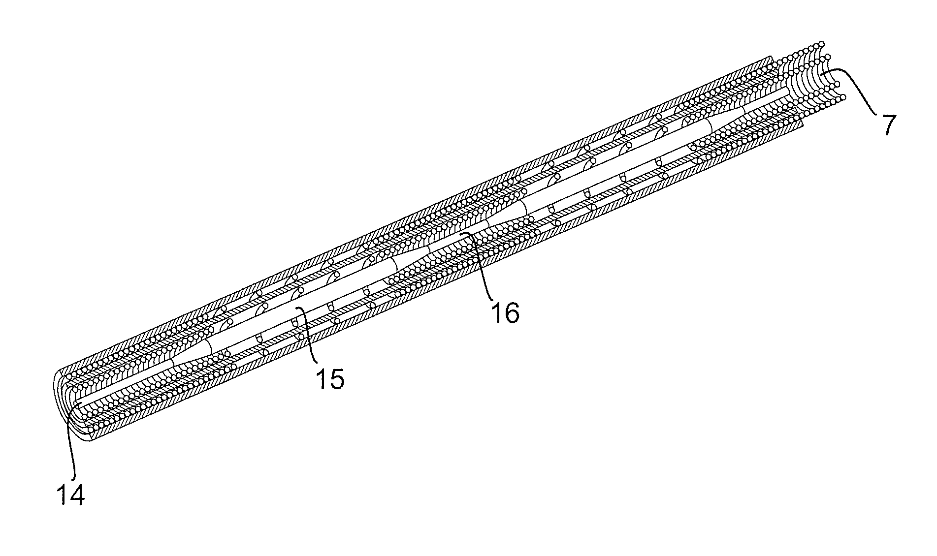
[0013]However, it is also possible to manufacture a support core which is sectioned in portions having different stiffness. In this way it is possible to set different stiffness in different portions of the support core. For example, to insert a support core having a highly flexible distal portion in order to increase the stiffness in a less degree in a distal tip portion than the rest of the lead to reduce the risk of penetration into the heart wall. Another possibility is to vary the flexibility along the entire length of the lead in order to get portions having high stiffness and intermediary portions having low stiffness, wherein the portions having high stiffness are adapted to be localised at sections of a MRI-compatible lead being highly flexible and the portions having low stiffness to be localised at sections of the MRI-compatible lead being less flexible. When inserted into the lumen of an MRI-compatible lead, the lead will accordingly adopt a more uniform flexibility along its length.
[0014]The varying stiffness along the length of the support core can be achieved in different ways, e.g. by forming the support core with varying cross sectional dimension along its length, by positioning reinforcing material at the locations where the stiffness should be increased or to anneal defined portions of a support core made of a material that will get a lasting increase of the flexibility when being warmed up.

Problems solved by technology

For example, a cardiac monitoring and controlling lead being too stiff and thin in the outermost distal end portion, could under certain circumstances penetrate into the heart wall and cause severe injuries.
However, the thin leads will still have to fulfil all mechanical requirements that the leads will have to withstand during their working life and with thinner and more flexible leads, the risk for fracture of the lead will increase, since the lead may not have the sufficient fatigue resistance that is required to withstand e.g. the movements of a beating heart.
However, when the cross sectional dimension of the lead, and hence the wire coils, is decreasing, also the stiffness of the lead will decrease.
However, the loosely wound sections of the lead will represent a weakened section of the lead which might lead to a subsequent fatigue fracture due to frequent movements inside the body, e.g. from a beating heart.

Method used


Image

  • Medical lead assembly and method for implantation thereof
  • Medical lead assembly and method for implantation thereof
  • Medical lead assembly and method for implantation thereof

Examples


first embodiment

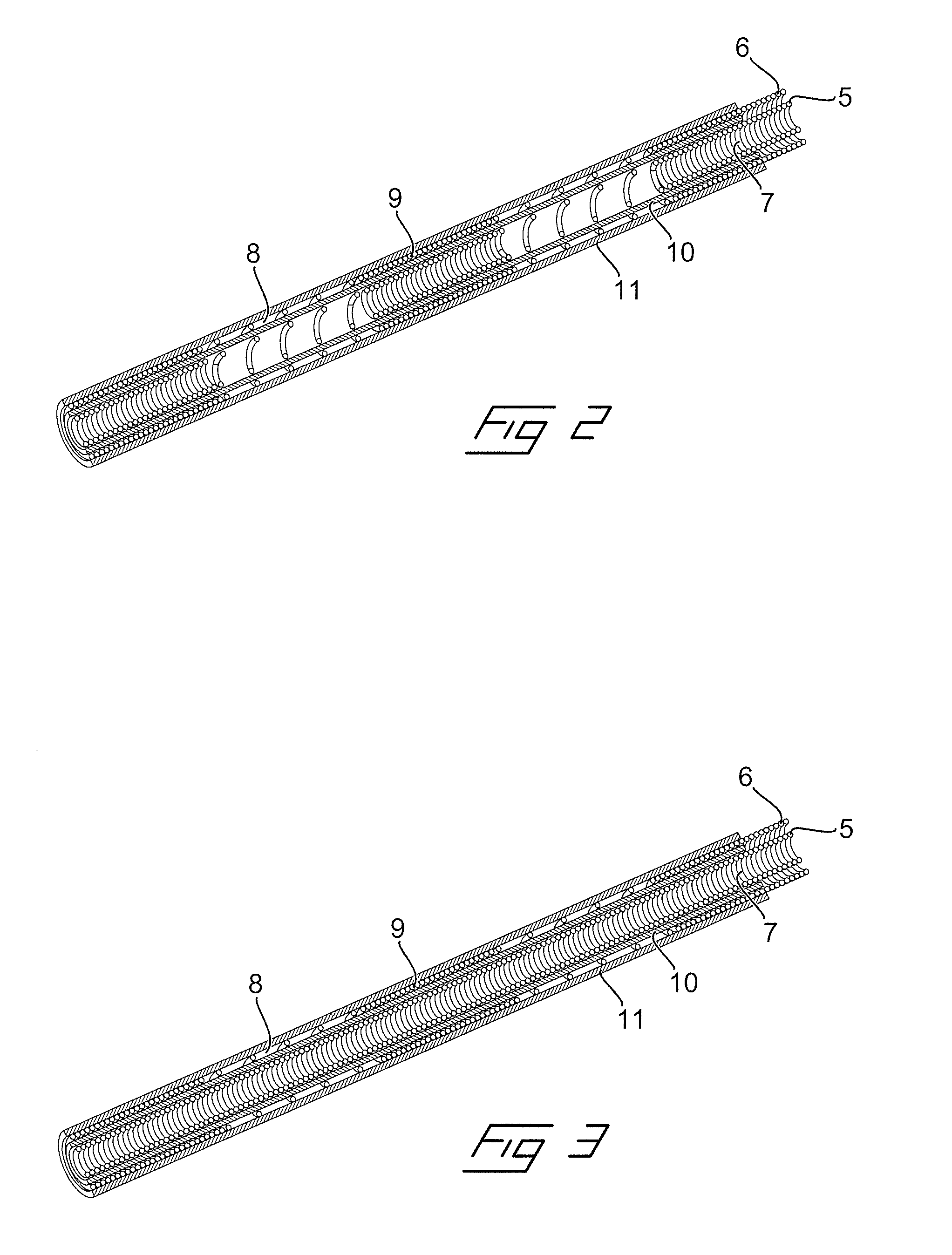
[0029]In FIGS. 2 and 3 are schematically illustrated two different embodiments of a new type of an implantable electrical lead, which are especially adapted for being compatible with MRI-fields. This has been achieved by arranging at least one of the outer and inner wire coils with alternating tightly wound coil sections 8 and loosely wound coil sections 9 having carefully adapted lengths and interrelation. In FIG. 2 is illustrated a first embodiment where both the inner wire coil 5 as well as the outer wire coil 6 are formed with alternating loosely wound coil sections 8 and tightly wound coil sections 9. In the embodiment in FIG. 3 on the other hand, only the outer wire coil 6 is formed with alternating loosely wound and tightly wound coil sections. The inner and outer wire coils are separated by inner and outer flexible tubes 10 and 11, respectively.

second embodiment

[0030]In both of these embodiments, the inner wire coil 5 is defining an inner lumen 7, into which a guide wire can be inserted for guiding the lead during implantation. This is illustrated in FIG. 4, where a lead having an entirely tightly wound inner coil 5, is shown with a straight guide wire 12 inserted in the lumen. This straight guide wire can be used when passing the lead through a vein into the heart. When the distal end of the lead is positioned inside a chamber of the heart, the straight guide wire can be retracted and a curved guide wire 13 having a preformed curve in the distal end, as shown adjacent the lead, can be inserted into the lumen. By rotating the lead with the curved guide wire inside, the distal end of the lead can be pivoted such that its tip abuts against heart tissue at a desired location and then the helix is rotated and hence screwed into the tissue for attachment.

[0031]One disadvantage with an implantable lead being formed with loosely wound coil secti...


PUM


Abstract

An assembly includes a medical implantable lead adapted to be attached with a distal end of the lead to an organ inside a human or animal body, the medical implantable lead being formed with an inner lumen extending along essentially the entire length of the lead. The assembly also includes a support core that has a desirable stiffness and a suitably cross sectional dimension such that it is insertable into the lumen (7) in order to increase the stiffness of the lead along its length during its working life when being implanted into a body. A method for implanting a medical implantable lead into a human or animal body makes use of such an assembly.

Description

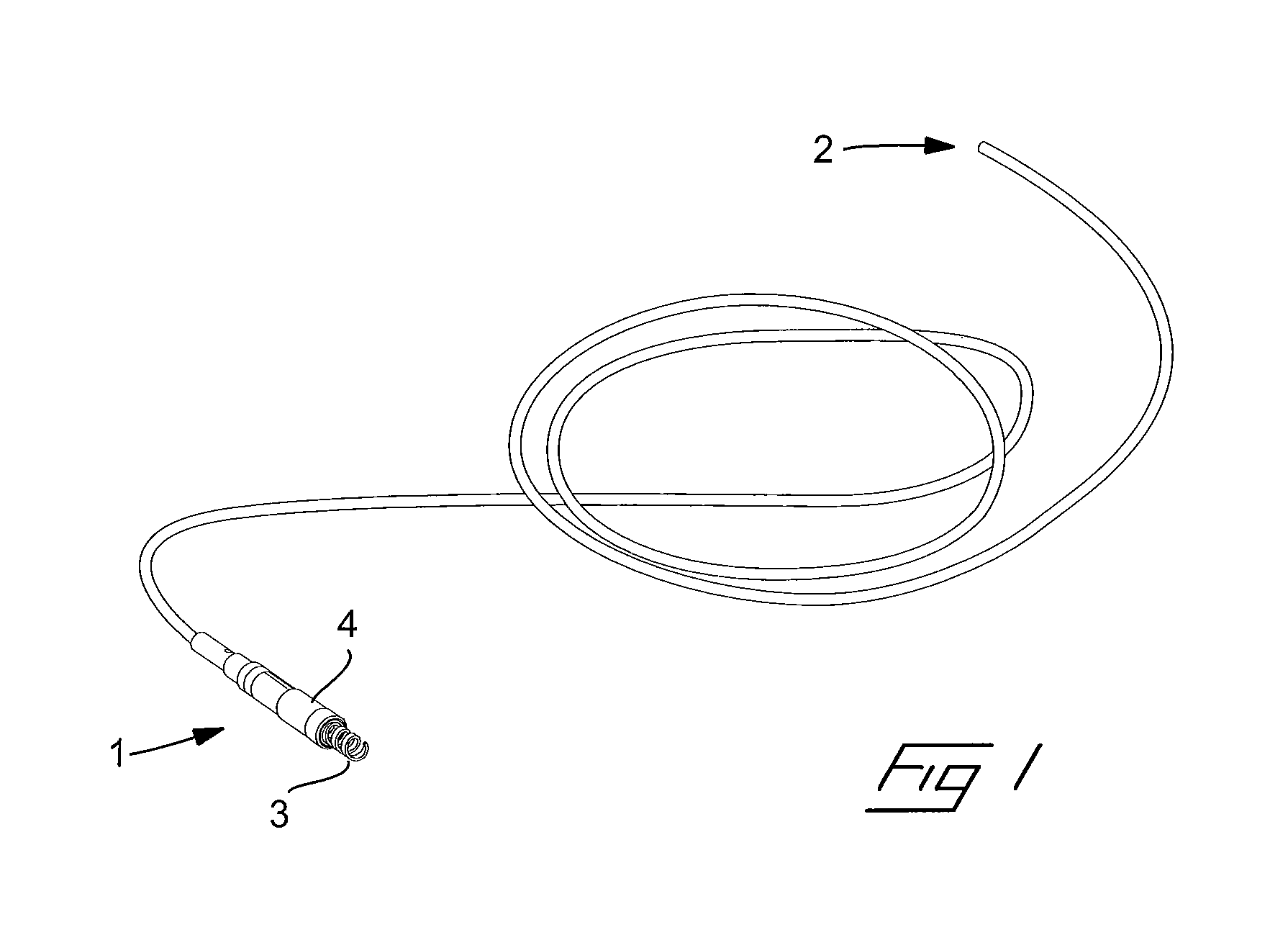
BACKGROUND OF THE INVENTION[0001]1. Field of the Invention[0002]The invention relates to a set comprising a medical implantable lead being adapted to be attached with a distal end of the lead to an organ inside a human or animal body, wherein the medical implantable lead is formed with an inner lumen extending along essentially the entire length of the lead.[0003]The invention also relates to a method for implanting a medical implantable lead into a human or animal body.[0004]2. Description of the Prior Art[0005]Medical implantable leads are used to connect a device located outside of the body or implanted just beneath the skin at a desired location, with an organ inside the body for monitoring and / or controlling of the organ. Mostly it is an electrical lead, which is adapted to receive and / or transmit electrical signals from and to the organ, respectively, such as for example an electrical lead for connecting a pacemaker or a defibrillator with a heart. However, it could also be so...

Claims


Application Information

Patent Timeline
Patent Type & Authority Patents(United States)
IPC IPC(8): A61N1/05
CPCA61N1/056A61N1/05A61M25/0054A61M2025/0063A61N2001/0578A61N2001/086A61N1/086
Inventor DJURLING, HENRIKHILL, ROLFSTEGFELDT, OLOFBROOME, .ANG.SASTRANDBERG, HANS
Owner ST JUDE MEDICAL
Learn More