System and method for pump-controlled cylinder cushioning

a hydraulic actuator and pump-controlled technology, applied in the direction of fluid couplings, servomotors, couplings, etc., can solve the problems of stroke, hydraulic actuators with limited position range, throttling flow through control valves,

Active Publication Date: 2013-06-04
PURDUE RES FOUND INC
View PDF13 Cites 15 Cited by
  • Summary
  • Abstract
  • Description
  • Claims
  • Application Information

AI Technical Summary

Benefits of technology

[0007]According to a first aspect of the invention, the system includes a hydraulic actuator adapted to move the implement. The actuator includes a piston that defines first and second chambers within the actuator and a piston rod coupled to the piston and to the implement. A variable displacement pump is coupled to the actuator for delivering a pressurized fluid to and receiving pressurized fluid from the chambers of the actuator. A sensor generates an output based on the position of the piston or the piston rod of the actuator. A controller controls the displacement of the variable displacement pump in response to the output of the sensor, wherein the controller is operable to execute an algorithm to reduce the flow rate of the fluid to the first chamber and from the second chamber of the actuator and thereby reduce the velocity of the piston of the actuator as the piston approaches an end of a piston stroke thereof within the actuator and prevent the piston from impacting the actuator at the end of the piston stroke.
[0008]According to a second aspect of the invention, the method includes using a variable displacement pump to deliver a pressurized fluid to and receive pressurized fluid from first and second chambers of a hydraulic actuator adapted to move the implement. The actuator comprises a piston that defines the first and second chambers and a piston rod coupled to the piston and to the implement. An output is generated based on the position of the piston or the piston rod of the actuator, and the displacement of the variable displacement pump is controlled in response to the output by reducing the flow rate of the fluid to the first chamber and from the second chamber of the actuator and thereby reduce the velocity of the piston as the piston approaches an end of a piston stroke thereof within the actuator and prevent the piston from impacting the actuator at the end of the piston stroke.
[0010]In view of the above, it can be seen that significant advantages of this invention include the ability to provide a cushioning effect without physically implementing conventional actuator cushions such as viscous dampers within the hydraulic circuit, and energy savings as a result of eliminating the need to throttle flow through directional control valves. Another advantage is the option for providing adjustment of the cushioning function based on the stroke position at which velocity of the actuator begins to slow and / or the rate of deceleration of the actuator, thereby providing greater flexibility for satisfying machine safety and operating requirements.

Problems solved by technology

However, throttling flow through control valves is known to waste energy.
Hydraulic actuators have a limited position range, or stroke.
Without some form of cushioning, the impact between the piston and cylinder can cause undesirable wear, vibration and operator discomfort.
For some machines, other safety problems such as vehicle instability may result from a sudden actuator stop.
However, manually regulating the actuator velocity requires skill and attention.

Method used


Image

  • System and method for pump-controlled cylinder cushioning
  • System and method for pump-controlled cylinder cushioning
  • System and method for pump-controlled cylinder cushioning

Examples


Embodiment Construction

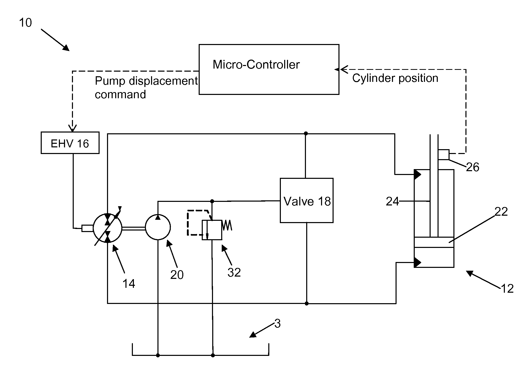
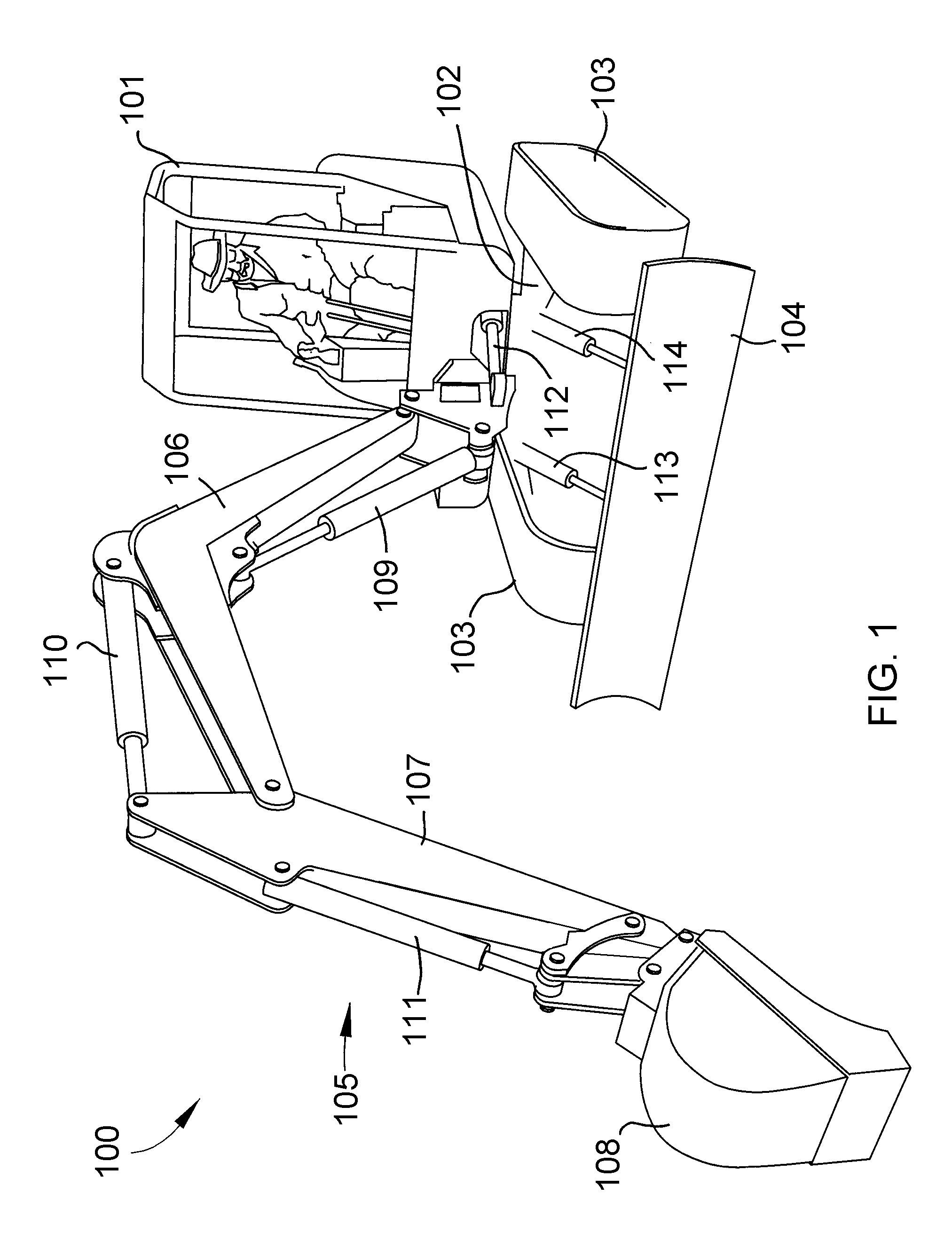
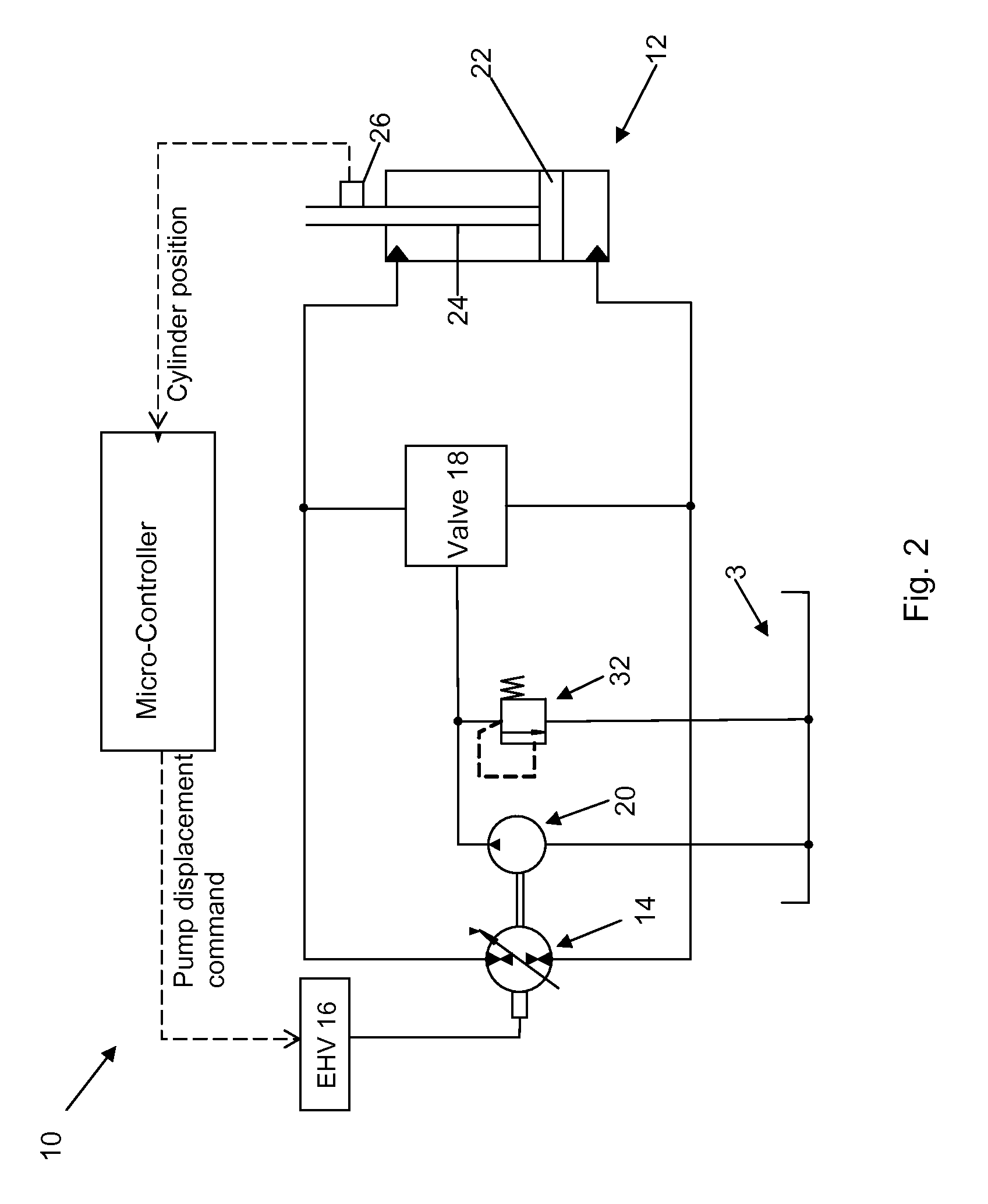
[0014]FIG. 2 schematically represents a system 10 for automatically controlling the position and velocity of a pump-controlled hydraulic actuator 12. The system 10 is represented in FIG. 2 as comprising a closed hydraulic circuit containing a pump-controlled hydraulic actuator 12 adapted to control the movement of an implement of an earthmoving machine, nonlimiting examples being any of the implements 104-108 of the excavator 100 of FIG. 1. As such, the actuator 12 can be exemplified by any of the linear actuators 109-114 of the excavator 100.

[0015]The system 10 of FIG. 2 further includes a variable displacement pump 14 connected to the hydraulic actuator 12, represented as a single-rod double-acting actuator. The pump 14 is powered by a primary power source (not shown), for example, an internal combustion engine. One or more valves 18 connect the hydraulic circuit to a suitable hydraulic fluid source, such as a charge pump 20 and reservoir 30 shown in FIG. 2, though the use of othe...


PUM


Abstract

A system and method for controlling the movement of an implement of an earthmoving machine. The system includes a hydraulic actuator adapted to move the implement. A variable displacement pump is coupled to the actuator for delivering a pressurized fluid to and receiving pressurized fluid from chambers within the actuator. A sensor generates an output based on the position of the actuator's piston or piston rod, and a controller controls the displacement of the variable displacement pump in response to the output of the sensor by executing an algorithm to reduce the flow rate of the fluid to and from the actuator's chambers and thereby reduce the velocity of the piston as it approaches an end of a piston stroke thereof and prevent the piston from impacting the actuator at the end of the piston stroke.

Description

CROSS REFERENCE TO RELATED APPLICATIONS[0001]This application claims the benefit of U.S. Provisional Application No. 61 / 111,748, filed Nov. 6, 2008, the contents of which are incorporated herein by reference.BACKGROUND OF THE INVENTION[0002]The present invention generally relates to systems for operating hydraulic circuits. More particularly, this invention relates to a system and method for pump-controlled cushioning of a hydraulic actuator used to control the position of a working implement on a mobile machine.[0003]Compact excavators, wheel loaders and skid-steer loaders are examples of multi-function machines whose operations involve controlling movements of various implements of the machines. FIG. 1 illustrates a compact excavator 100 as having a cab 101 mounted on top of an undercarriage 102 via a swing bearing (not shown) or other suitable device. The undercarriage 102 includes tracks 103 and associated drive components, such as drive sprockets, rollers, idlers, etc. The exca...

Claims


Application Information

Patent Timeline
Patent Type & Authority Patents(United States)
IPC IPC(8): F16D31/02F15B15/22F01B31/12
CPCE02F9/2207E02F9/2228F15B11/048F15B21/08E02F9/2289E02F9/2214F15B2211/20546F15B2211/27F15B2211/6336F15B2211/785F15B2211/20561E02F9/22F15B11/02E02F3/43
Inventor WILLIAMSON, CHRISTOPHER ALANIVANTYSYNOVA, MONIKA MARIANNE
Owner PURDUE RES FOUND INC
Why Eureka
Try Eureka