Screen-printing frame

a frame and screenprinting technology, applied in printing, door/window protective devices, coatings, etc., can solve the problems of destroying the mesh, reducing the service life of the frame, and affecting the quality of the screenprinting, so as to reduce or avoid the effect of tearing the mesh

Active Publication Date: 2013-06-04
NISWONGER JOHN O H
View PDF64 Cites 1 Cited by
  • Summary
  • Abstract
  • Description
  • Claims
  • Application Information

AI Technical Summary

Benefits of technology

[0013]A simple hand tool for stretching the mesh on the frame includes a griping portion, a bearing portion, and an optional hinge between the gripping portion and the bearing portion. The gripping portion may be used for gripping the locking strip slot and pulling on the movable frame member to stretch the mesh. The bearing portion may be used for leveraging against the rigid frame to pull on the gripping portion. The hinge may be used to maintain a angle between the gripping portion and the locking strip slot during translation of the movable frame member. An offset of the mesh from the gripping surface can reduce or avoid tearing of the mesh by the gripping portion.
[0014]A simple hand tool for removing the mesh from the frame includes a gripping portion and a wedge. The gripping portion of the removal tool may be used for gripping the locking strip slot and pulling to release the movable frame member from the frame under tension. The wedge may be inserted between angled surfaces of the movable frame member and the frame while pulling to separate and release the movable frame member from the frame. An optional catch may be used for preventing the released movable frame member from launching under tension of the mesh on the movable frame member. The mesh may be removed from the movable frame member once tension on the mesh is released.

Problems solved by technology

Unfortunately, the glues can degrade due to exposure to chemicals during printing.
Moreover, stretched frames take up space during storage.
Removing mesh for reuse of the frame destroys the mesh and typically involves the use of environmentally hazardous solvents.
Some of these glues and solvents are presently being outlawed in various jurisdictions and may someday become unavailable for use anywhere.
Unfortunately, it is difficult to load the fabric evenly and work the locking strip along the length of the groove because the locking strip catches on the fabric during insertion and removal.
Unfortunately, the stretching apparatus is complex, expensive, bulky, heavy, and slow, and is generally mounted to a table or fixed surface.
Attaching the second inverted “T” groove to the stretching apparatus, stretching the mesh, and then releasing the second “T” groove are cumbersome operations that take substantial time and complicated manipulations.
The resulting stretched frame is heavy.

Method used


Image

  • Screen-printing frame
  • Screen-printing frame
  • Screen-printing frame

Examples


Embodiment Construction

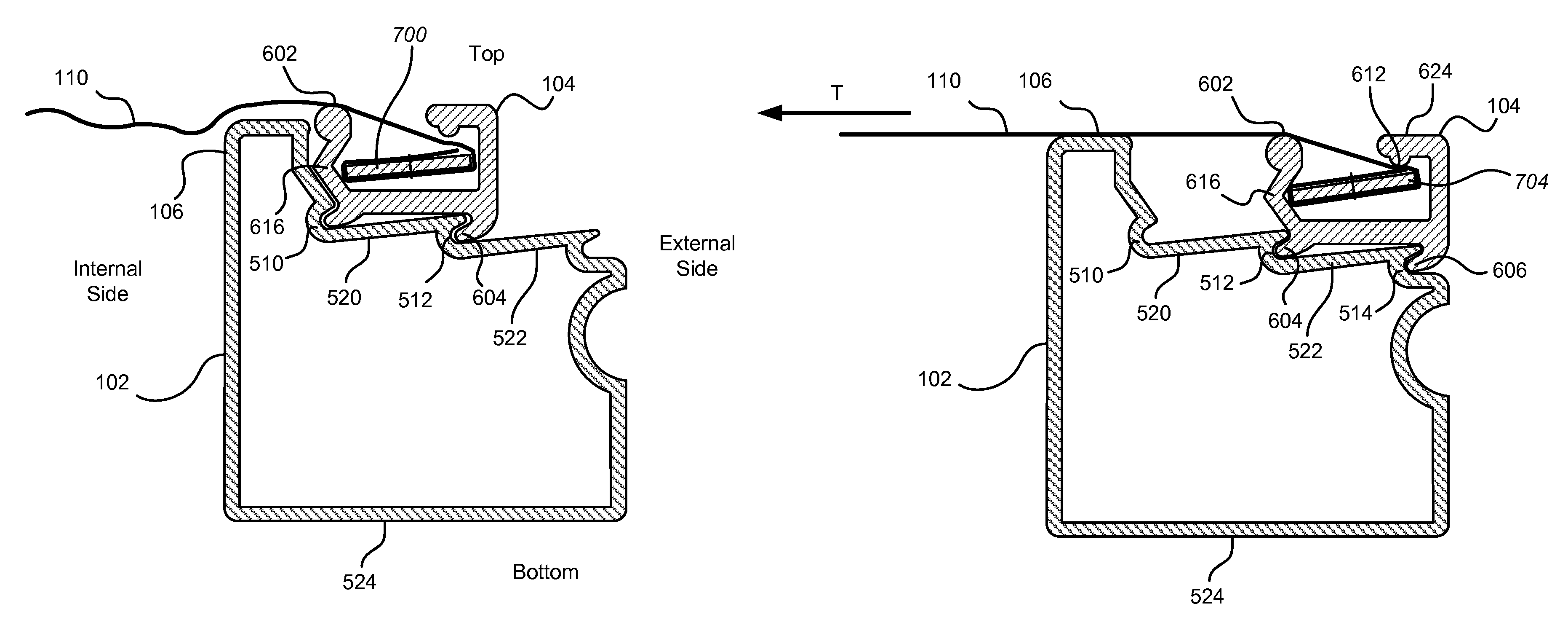
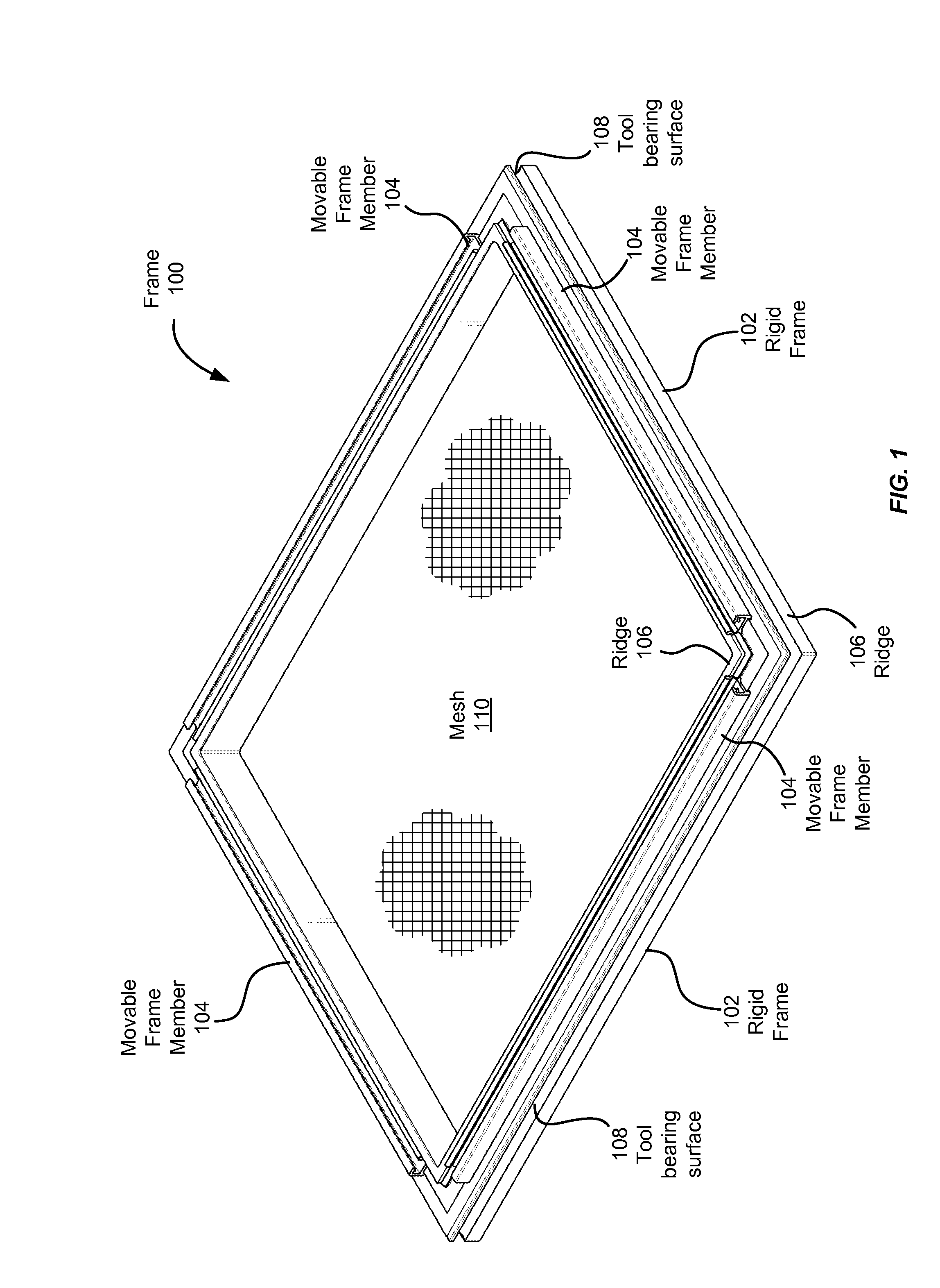
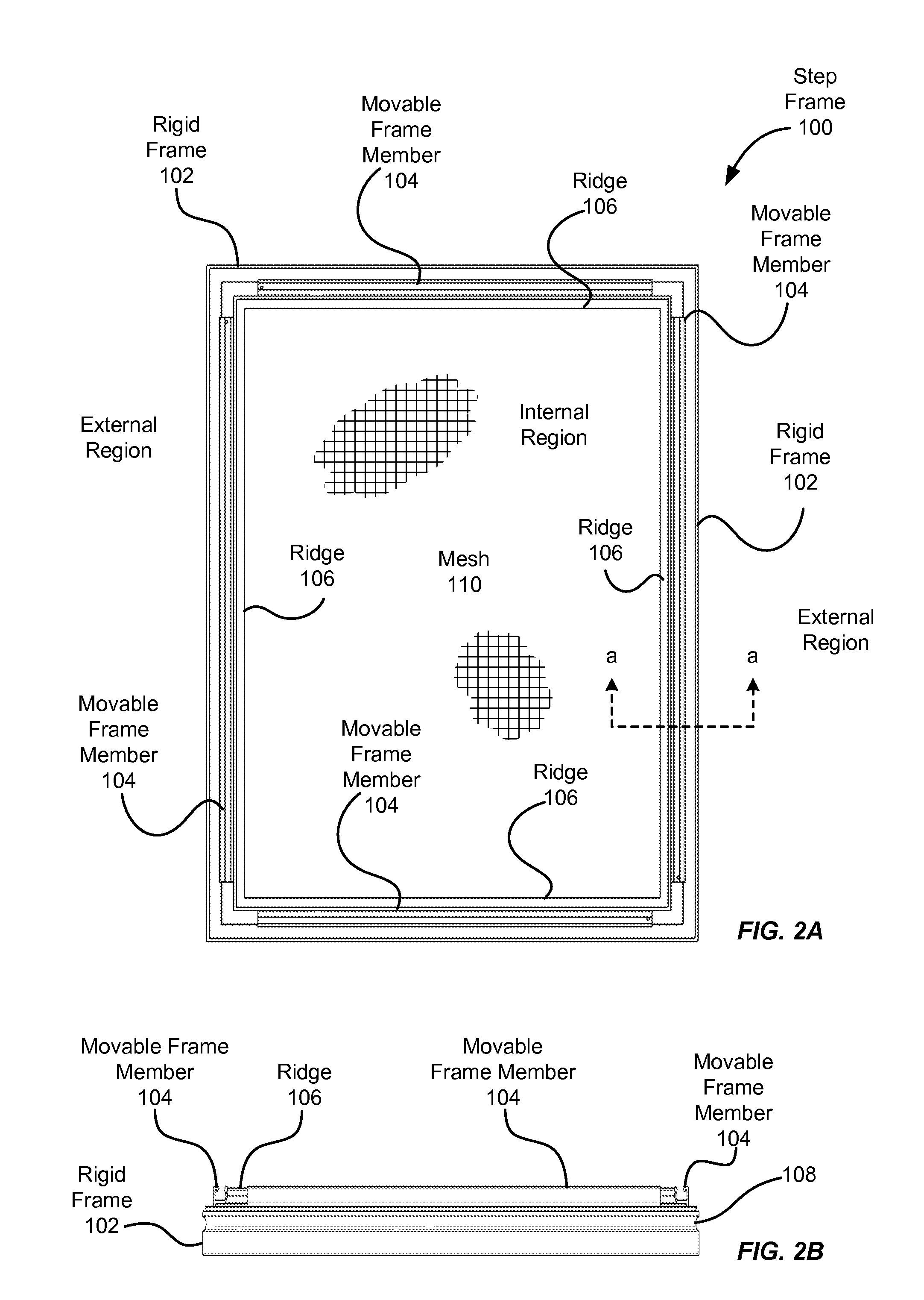
[0039]FIG. 1 is a perspective view of an embodiment of a frame 100 for screen tensioning and printing, in accordance with aspects of the invention. FIGS. 2A and 2B are a top plan view and a side elevation, respectively, of the frame 100 of FIG. 1. The frame 100 includes a rigid frame 102 and movable frame members 104. The frame 100 may be characterized as having an internal region or internal side and an external region or side. The internal region is bounded by the frame and includes the plane and center of the frame 100. The rigid frame 102 includes a ridge 106. The ridge illustrated in FIG. 1 is continuous around a periphery of the rigid frame 102 along an inner side and may separate the internal side of the frame 100 from the external side. The rigid frame further includes a tool bearing surface 108 comprising a groove disposed longitudinally along the external side of the rigid frame and substantially continuous around the periphery the rigid frame 102. Mesh 110 is suspended on...


PUM

PropertyMeasurementUnit
angleaaaaaaaaaa
frictionaaaaaaaaaa
weightaaaaaaaaaa

Abstract

A system for attaching mesh to a frame and applying tension to the mesh is described. The system includes a locking strip slot in a movable frame member that permits mesh and an attached locking strip to be inserted into the slot from the top. The locking strip may be asymmetric. The system further includes a rigid frame that can hold the movable frame member under tension. The system also includes gripping the movable frame member at the locking strip slot to apply tension to the mesh. A simple hand tool may be used for engaging the locking strip slot and leveraging against the rigid portion of the frame to apply the tension. A simple hand tool may be used for separating the movable frame member from the rigid frame to remove the mesh.

Description

CROSS-REFERENCE TO RELATED APPLICATIONS[0001]This application claims priority and benefit of U.S. provisional patent application No. 61 / 231,012 titled “Silkscreen Frame,” filed on Aug. 3, 2009, and U.S. provisional patent application No. 61 / 312,671 titled “Roller Frame Stretcher,” filed on Mar. 11, 2010, and U.S. provisional patent application No. 61 / 370,430 titled “SCREEN-PRINTING FRAME AND TOOL AND SCOOP COATER,” filed on Aug. 3, 2010.[0002]This application is a continuation in part of and claims priority and benefit of pending U.S. patent application Ser. No. 12 / 832,979, titled “APPARATUS AND METHOD FOR SCREEN TENSIONING,” filed Jul. 8, 2010, which is a continuation of U.S. patent application Ser. No. 11 / 827,729, filed on Jul. 13, 2007, now U.S. Pat. No. 7,752,963, which in turn claims priority and benefit of U.S. provisional patent application No. 60 / 830,712 titled “Improved Apparatus and Method for Screen Tensioning,” filed on Jul. 13, 2006.[0003]This application is a continuat...

Claims


Application Information

Patent Timeline
Patent Type & Authority Patents(United States)
IPC IPC(8): B05C17/06
CPCB41F15/36B44D3/185B41F15/34
Inventor NISWONGER, JOHN O. H.
Owner NISWONGER JOHN O H
Why Eureka
Try Eureka