Apparatus and process to extract heat and to solidify molten material particles

Inactive Publication Date: 2002-02-26
VIVIANE VASCONCELOS VILELA LTD
View PDF13 Cites 6 Cited by
  • Summary
  • Abstract
  • Description
  • Claims
  • Application Information

AI Technical Summary

Benefits of technology

It can be further provided with at least one low pressure gas duct providing a flow of a low pressure dispersing / cooling agent which substantially transversely traverses said flow of particles of molten or semi-molten material, in order to enhance the dispersion and cooling-off effects.
The transporting device is also provided with a sloping device, which allows the inclination of the transporting device to be varied, in order to make possible the particles to remain a shorter or longer period on the transporting device so as to give the particles time enough for cooling-off.
A hopper can be further provided, which serves to collect the dispersed particles and to carry them onto the transporting device so as to prevent any particles from being launched outside the transporting device. The hopper is provided with a vibrator, which provides a vibrating movement to the hopper to prevent the particles which are still cooling-off from being agglomerated again.
Cooling water pipes could be provided to eject a flow of cooling water onto the internal walls of the hopper and also onto the transporting device, which assist cooling of the dispersed particles. This water cooling flow serves also to protect the walls of the hopper against heat.

Problems solved by technology

Prior granulating processes produce granules of different sizes, which should be separated from the water after quenching, requiring the use of auxiliary separating equipment, therefore increasing costs.
Another problem with known processes of quenching by water is the risk of explosions.
It is known that contact between extremely hot molten material particles and water results in violent reactions, which can jeopardize the operators and the facilities.
The quenching of the particles can occur inside of water reservoirs having an explosion-proof shield in order to preclude such risking conditions that might cause safety problems, therefore increasing the costs of the equipment.
The fact of the dispersion of the particles is based on an expansion of water into a closed chamber is a drawback for the use of the apparatus and the process disclosed in U.S. Pat. No. 5,667,147, as it requires an accurate control of the volumes of injected water for the desired expansion to occur, which is not that simple to accomplish.
This makes the operation critical and can eventually impair achievement of the goal, that is, the obtainment of solidified granules of molten material.

Method used


Image

  • Apparatus and process to extract heat and to solidify molten material particles
  • Apparatus and process to extract heat and to solidify molten material particles
  • Apparatus and process to extract heat and to solidify molten material particles

Examples


first embodiment

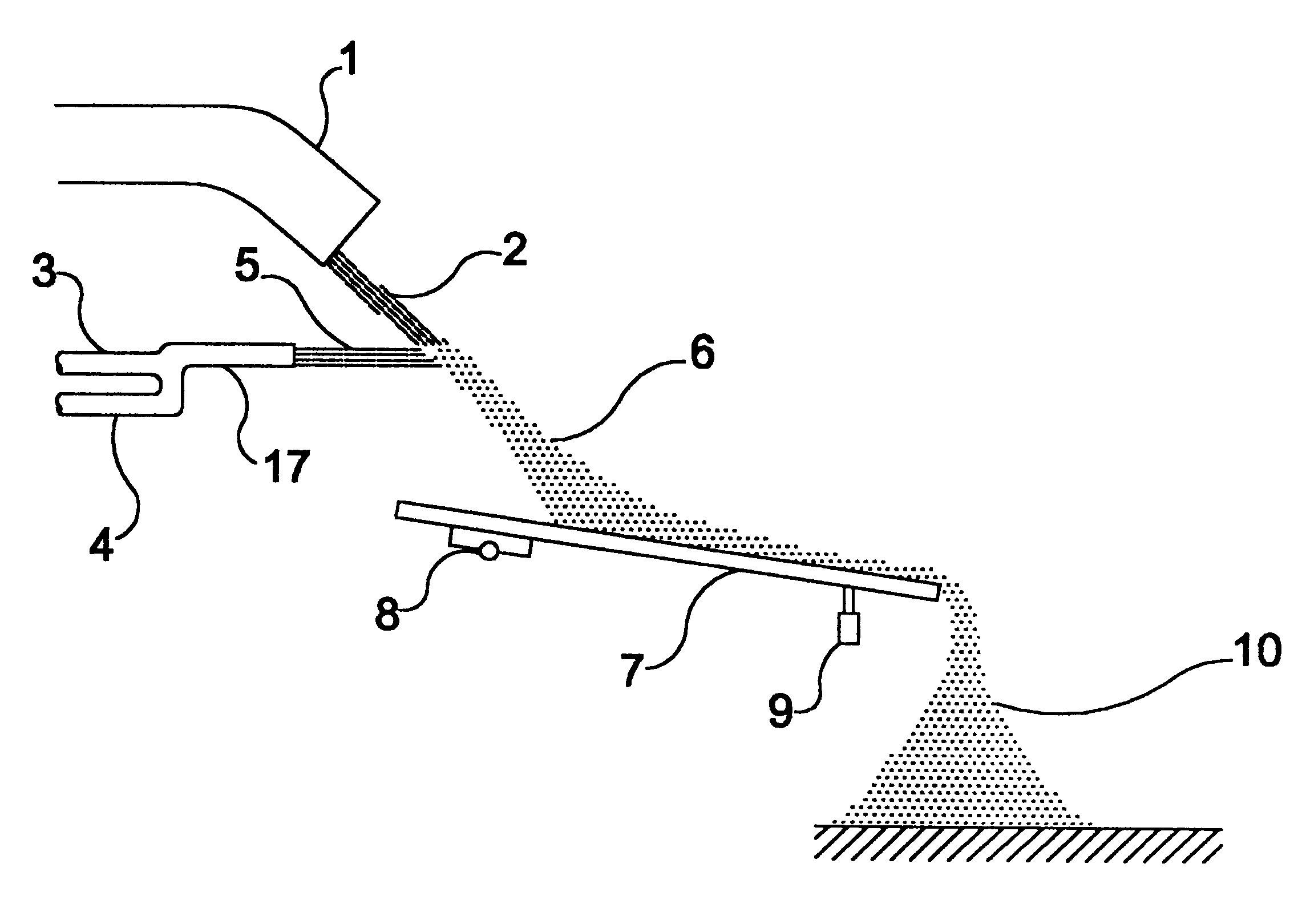
FIG. 1 depicts an apparatus object of the invention. A downward molten material flow 2 flows by gravity from a launder 1 and is traversed by a high pressure dispersing / cooling flow 5 coming from a dispersing / cooling agent ejector 17.

In the present embodiment the ejector 17 comprises a high pressure gas tube 4, which provides a flow of gas at a high pressure, e.g. air or nitrogen, the tube 4 being interconnected to an ejection water tube 3, which provide a flow of ejection water, therefore a high pressure dispersing / cooling flow 5 is provided at the outlet of the ejector 17.

The high pressure dispersing / cooling flow 5 substantially transversely traverses the downward molten material flow 2, in order to provoke dispersion of the latter in particles of molten or semi-molten material 6, provoking said particles 6 to cool-off at the same time.

The dispersed particles 6 of molten or semi-molten material next impinge onto a transporting device 7 which carry them to their collecting area. Som...

second embodiment

FIG. 3 depicts an apparatus to extract heat and to solidify molten material particles according to the present invention. This embodiment basically comprises the some parts previously described with regard to FIGS. 1 and 2, and for the sake of simplification it will not be described here again how occurs the dispersion of the molten material flow 2 into particles of molten or semi-molten material 6, as in this embodiment such dispersion occurs in the same way as previously described.

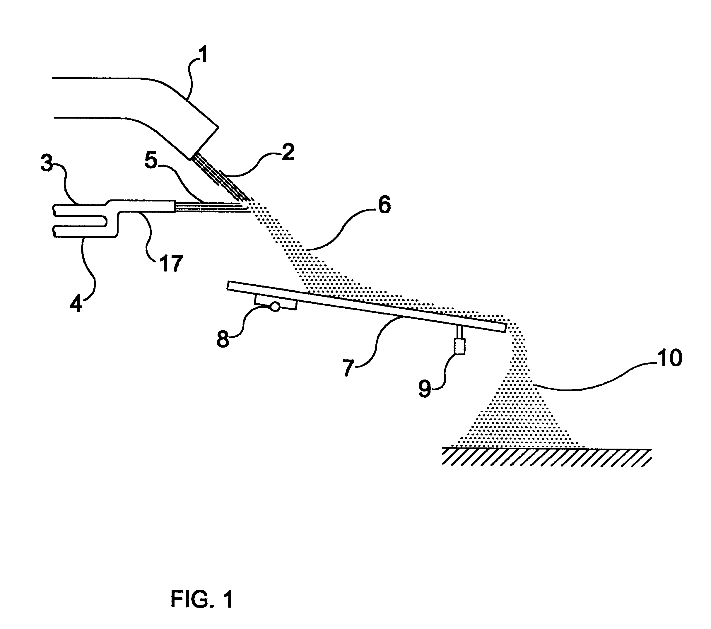
It should be pointed out that although the low pressure gas duct 11 is used in this embodiment and intended to provide a low pressure dispersing / cooling flow 12, said low pressure gas duct 11 could be omitted, depending on the features of the molten material flow which is to be dispersed into particles 6.

The apparatus shown in FIG. 3 differs from the previously shown apparatuses in comprising the use of a hopper 15, which serves to collect the dispersed particles 6, carrying them onto the transporting de...


PUM

PropertyMeasurementUnit
Pressureaaaaaaaaaa
Flow rateaaaaaaaaaa
Heataaaaaaaaaa

Abstract

The present invention relates to an apparatus and a process to extract heat and to solidify molten material particles. A flow of molten material is traversed by a high pressure dispersing / cooling flow to form particles of molten or semi-molten material. The particles impinge against a transporting device, which transport them to a collecting place. The transporting device is provided with a vibrator, which provides a vibrating movement to the transporting device to prevent the particles which are still cooling-off from being agglomerated again. A flow of a low pressure dispersing / cooling could be provided, which substantially transversely traverses said flow of particles of molten or semi-molten material which fall towards the transporting device, in order to enhance the dispersion and cooling-off effects of the particles. A hopper could be provided to collect the particles and to carry them to the transporting device. Cooling water pipes could be provided to eject a flow of cooling water onto the internal walls of the hopper and also onto the transporting device, which assist cooling of the dispersed particles.

Description

This invention relates to a process and an apparatus to produce solid particles from a flow of molten material.STATE OF THE ARTA number of processes are used to produce solid particles from a flow of molten material, which are known as granulating processes generally, granulating processes comprise pouring a flow of a molten material into a granulating chamber, where this downward flow of molten material is atomized by a dispersion member, causing this flow to disperse in a number of particles of molten material.Said particles of molten material are quenched by contacting a cooling agent, usually water, in order to make a rapid cooling-off of the particles, thus forming the desired granules. A large volume of water is usually used to quench the dispersed particles of molten materials, in a relationship ranging from nine to twenty parts of water for one part of molten material.Prior granulating processes produce granules of different sizes, which should be separated from the water af...

Claims


Application Information

Patent Timeline
IPC IPC(8): C21B3/00C21B3/08C04B5/02B01J2/02C21C1/02C21C5/28C21C7/00C22B7/04F27D15/02
CPCC21B3/08C21B2400/062C21B2400/034C21B2400/024C21B2400/026
Inventor ARANA, DAVID
Owner VIVIANE VASCONCELOS VILELA LTD
Why Eureka
Try Eureka