Biased wall ink tank with capillary breather

a flexible wall, ink tank technology, applied in printing and other directions, can solve the problems of air bubbles in the printhead, limited pigment particle size that can be used, defective images during printing process, etc., and achieve the effect of increasing the internal volume of the reservoir

Inactive Publication Date: 2013-06-04
EASTMAN KODAK CO
View PDF15 Cites 39 Cited by
  • Summary
  • Abstract
  • Description
  • Claims
  • Application Information

AI Technical Summary

Problems solved by technology

Such settling of pigments particles, especially for larger pigment particles (e.g. larger than 30 nanometers), can result in defective images during the printing process.
As a result, an ink tank using capillary media to store ink can lead to a limitation in pigment particle size that can be used.
Such a limitation can be disadvantageous because such larger particles can be beneficial for providing higher optical density in printed regions.
However, it is also desirable for the flexible wall to have low permeability to air, in order to keep air from passing through the flexible wall and being absorbed into the ink, which can result in air bubbles in the printhead.
However, additional layers for low air permeability can reduce the degree of flexibility of the flexible wall.
However, typically such a one-way valve has a substantial cracking pressure at which the valve opens, leading to fluctuations in the regulated pressure, as the negative pressure in the reservoir needs to build up sufficiently to open the one-way valve.
A difficulty in providing such a small hole in an ink container is that ink containers are typically injection molded, and a 50 micron molding pin to provide such a hole in the container would not be sufficiently robust for injection molding large numbers of ink containers.

Method used


Image

  • Biased wall ink tank with capillary breather
  • Biased wall ink tank with capillary breather
  • Biased wall ink tank with capillary breather

Examples


Embodiment Construction

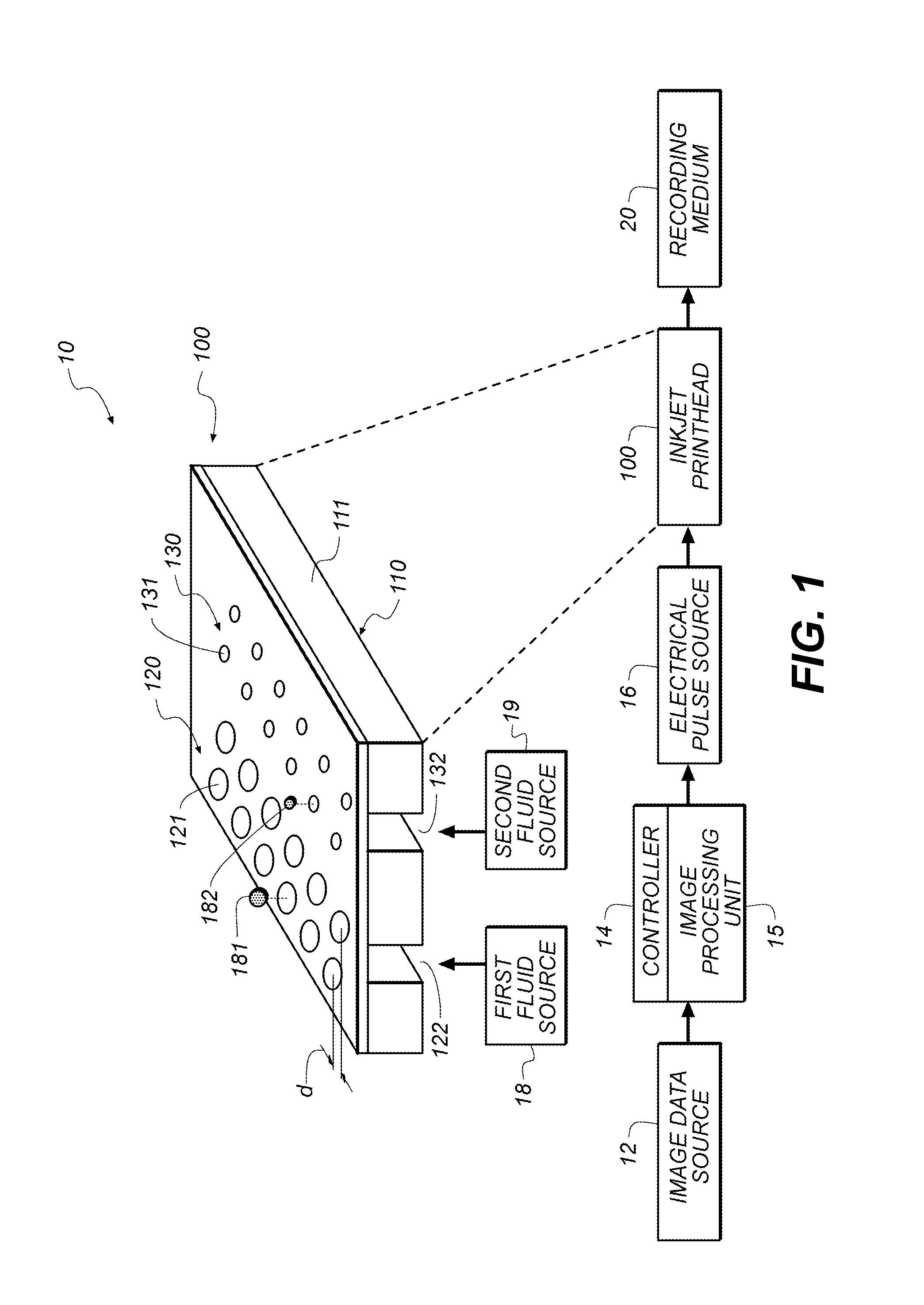
[0031]Referring to FIG. 1, a schematic representation of an inkjet printer system 10 is shown, for its usefulness with the present invention and is fully described in U.S. Pat. No. 7,350,902, and is incorporated by reference herein in its entirety. Inkjet printer system 10 includes an image data source 12, which provides data signals that are interpreted by a controller 14 as being commands to eject drops. Controller 14 includes an image processing unit 15 for rendering images for printing, and outputs signals to an electrical pulse source 16 of electrical energy pulses that are inputted to an inkjet printhead 100, which includes at least one inkjet printhead die 110.

[0032]In the example shown in FIG. 1, there are two nozzle arrays. Nozzles 121 in the first nozzle array 120 have a larger opening area than nozzles 131 in the second nozzle array 130. In this example, each of the two nozzle arrays has two staggered rows of nozzles, each row having a nozzle density of 600 per inch. The ...


PUM


Abstract

An ink tank including a reservoir for holding ink, the reservoir including a flexible wall for adjusting an internal volume of the reservoir; a biasing element for applying a force to the flexible wall that tends to increase the internal volume of the reservoir; an ink supply port for delivering ink from the reservoir to a printhead; and a breather element, at least a portion of which is disposed inside the reservoir, including a capillary material in contact with ink in the reservoir, wherein the breather element is configured to allow air to enter the reservoir in response to an internal pressure of the reservoir being less than atmospheric pressure outside the ink tank by an amount that is related to a property of the biasing element and a capillary pressure of the breather element.

Description

CROSS-REFERENCE TO RELATED APPLICATIONS[0001]Reference is made to commonly assigned, co-pending U.S. patent application Ser. No. 12 / 974,038, filed concurrently herewith, entitled: “Forming an Ink Tank with Capillary Breather”, the disclosure of which is incorporated herein.FIELD OF THE INVENTION[0002]The present invention relates generally to an ink tank for an inkjet printhead, and more particularly to pressure regulation for an ink tank having a spring-biased flexible wall.BACKGROUND OF THE INVENTION[0003]An inkjet printing system typically includes one or more printheads and their corresponding ink supplies. Each printhead includes an ink inlet that is connected to its ink supply and an array of drop ejectors, each ejector consisting of an ink pressurization chamber, an ejecting actuator and a nozzle through which droplets of ink are ejected. The ejecting actuator may be one of various types, including a heater that vaporizes some of the ink in the pressurization chamber in order...

Claims


Application Information

Patent Timeline
Patent Type & Authority Patents(United States)
IPC IPC(8): B41J2/175B41J2/17
CPCB41J2/17513B41J2/17556
Inventor PRICE, BRIAN G.PICKERING, JAMES EDWARDHOFF, JOSEPH W.
Owner EASTMAN KODAK CO
Why Eureka
Try Eureka