Diluent shroud for combustor

a combustor and diluent technology, applied in the field of combustor diluent shroud, introduction of diluent flow into the combustor, can solve the problems of reduced efficiency and problem of operability in the combustor

Inactive Publication Date: 2013-06-04
GENERAL ELECTRIC CO
View PDF19 Cites 77 Cited by
  • Summary
  • Abstract
  • Description
  • Claims
  • Application Information

AI Technical Summary

Problems solved by technology

When the diluent is drawn toward the center hub, the diluent effectiveness is reduced and may cause operability problems in the combustor such as blow out.

Method used


Image

  • Diluent shroud for combustor
  • Diluent shroud for combustor
  • Diluent shroud for combustor

Examples


Embodiment Construction

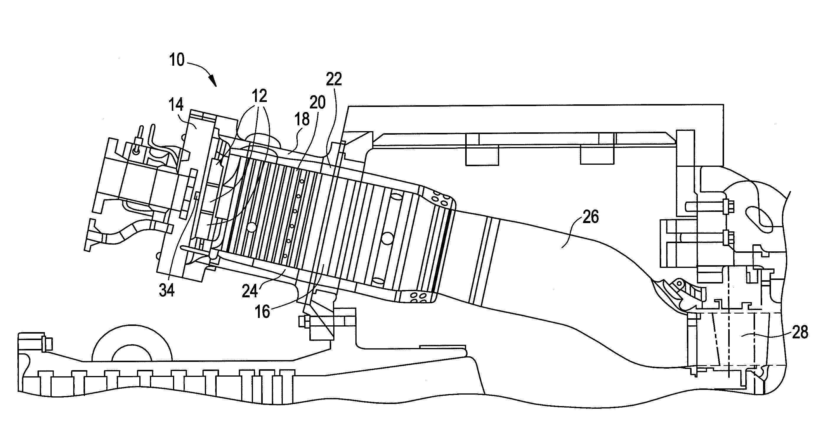
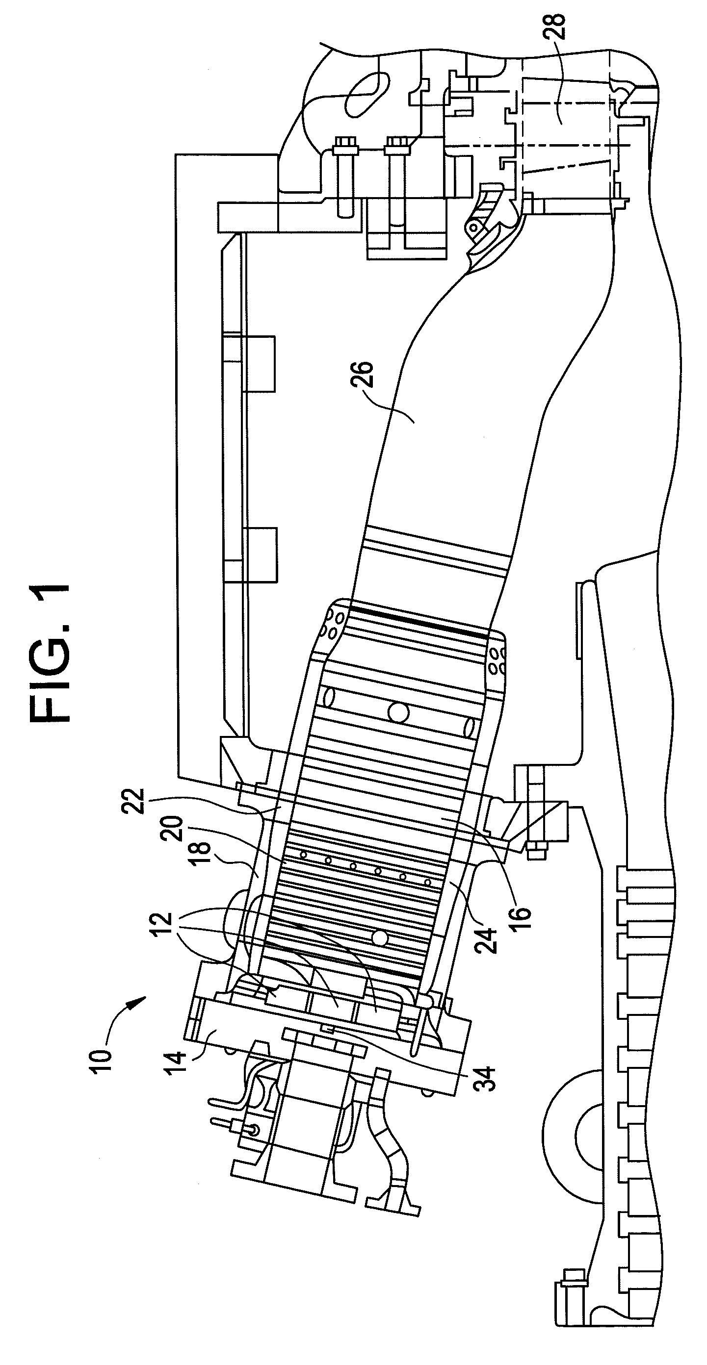
[0012]Shown in FIG. 1 is an embodiment of a combustor 10. The combustor 10 includes a plurality of fuel nozzles 12 disposed at an end cover 14. Compressed air and fuel are directed through the end cover 14 to the plurality of fuel nozzles 12, which distribute a mixture of the compressed air and the fuel into the combustor 10. The combustor 10 includes a combustion chamber 16 generally defined by a casing 18, a liner 20 and a flow sleeve 22. In some embodiments, the flow sleeve 22 and the liner 20 are substantially coaxial to define an annular air passage 24 that may enable passage of an airflow therethrough for cooling and / or entry into the combustion chamber 16 via, for example a plurality of perforations (not shown) in the liner 20. The casing 18, the liner 20 and the flow sleeve 22 are configured to provide a desired flow of the mixture through a transition piece 26 toward a turbine 28.

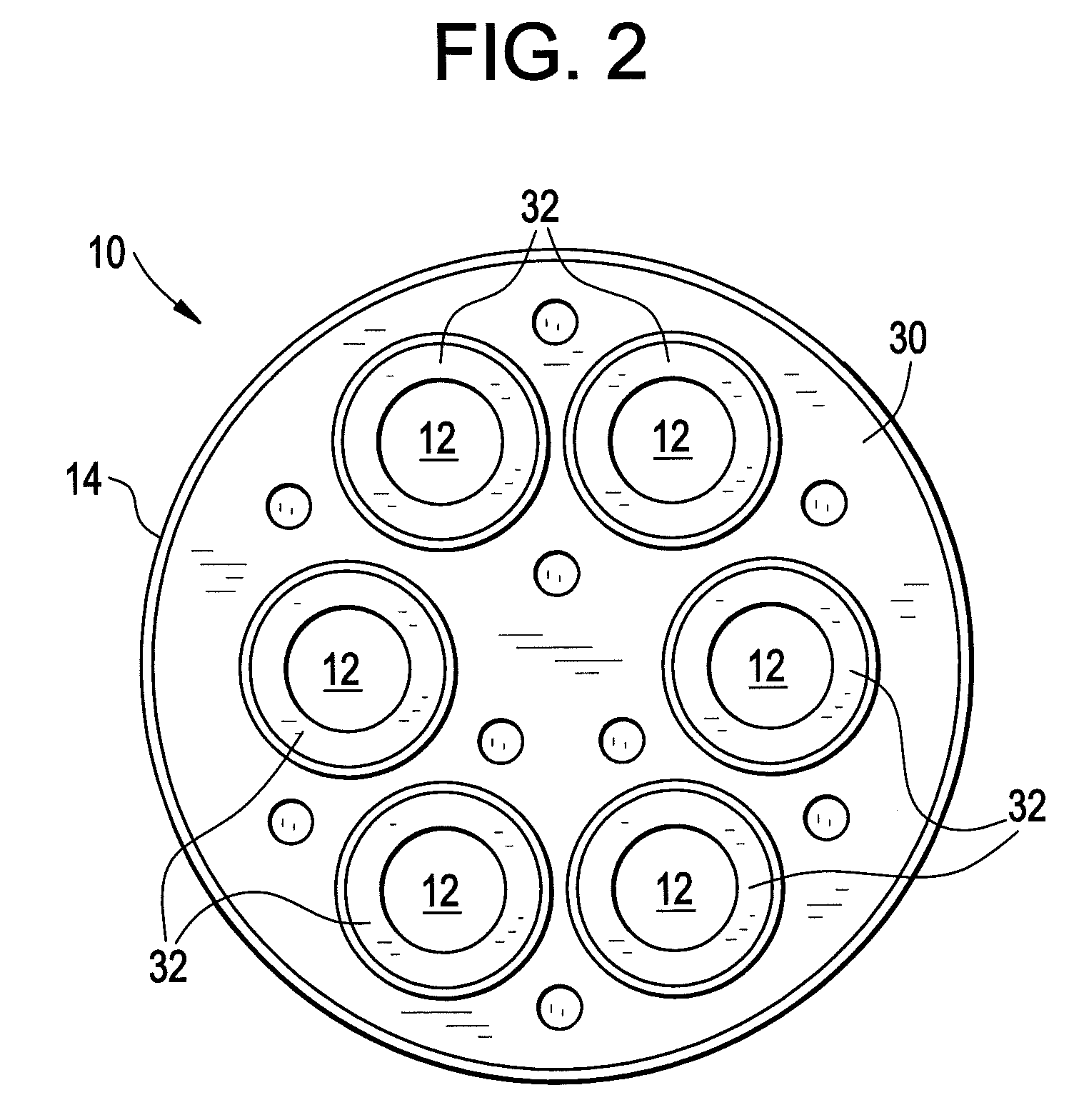
[0013]Referring now to FIG. 2, the combustor 10 includes a baffle plate 30 having six baffle ho...


PUM


Abstract

Disclosed is a combustor including a baffle plate having at least one through baffle hole and at least one fuel nozzle extending through the at least one through baffle hole. At least one diluent shroud is affixed to the at least one baffle plate and is configured to guide a diluent flow toward a mixing chamber of the at least one fuel nozzle. Further disclosed is a method for introducing a diluent flow into a mixing chamber of a fuel nozzle including urging the diluent flow from a plenum through a baffle plate gap between a baffle plate and an outer surface of the fuel nozzle. The diluent flow is directed via at least one diluent shroud extending from the baffle plate toward a plurality of air swirler holes extending through a fuel nozzle tip. The diluent flow is flowed through the plurality of air swirler holes into the mixing chamber.

Description

BACKGROUND OF THE INVENTION[0001]The subject invention relates generally to combustors. More particularly, the subject invention relates to the introduction of diluent flow into a combustor.[0002]Combustors typically include one or more fuel nozzles that introduce a fuel or a mixture of fuel and air to a combustion chamber where it is ignited. In some combustors, the fuel nozzles extend through holes disposed in a baffle plate of the combustor. In these combustors, it is often advantageous to introduce a volume of diluent, often nitrogen or steam, to the combustor to reduce NOx and / or CO emissions and / or augment output of the combustor. The diluent is urged from a chamber through a gap between the baffle plate and each fuel nozzle then flows along a periphery of the fuel nozzle where a portion of the diluent enters a plurality of air swirler holes and is mixed with air and introduced into the fuel nozzle. Under some conditions, however, the diluent is drawn toward a center hub of th...

Claims


Application Information

Patent Timeline
Patent Type & Authority Patents(United States)
IPC IPC(8): F23C5/00
CPCF23R3/28F23R3/10
Inventor BERRY, JONATHAN DWIGHTLIPINSKI, JOHN JOSEPHSIMONS, GIRARD ALBERTSOM, ABHIJIT
Owner GENERAL ELECTRIC CO
Why Eureka
Try Eureka