Electrical connector with sacrificial component

a technology of electrical connectors and components, applied in the direction of line connector maintenance, line/current collector details, coupling device connections, etc., can solve the problems of high cost, time-consuming, potentially dangerous voltages

Inactive Publication Date: 2013-06-04
THOMAS & BETTS INT INC
View PDF19 Cites 8 Cited by
  • Summary
  • Abstract
  • Description
  • Claims
  • Application Information

AI Technical Summary

Problems solved by technology

Because such voltages are potentially very dangerous, it is typically necessary for personnel to confirm that the power is disconnected before commencing work or repair.
Problematically, after a cable is “spiked,” the utility is required to replace or re-terminate the cable or increase its length by adding a splice and additional cable in order to reconnect to the system.
This is costly and time consuming.

Method used


Image

  • Electrical connector with sacrificial component
  • Electrical connector with sacrificial component
  • Electrical connector with sacrificial component

Examples


Embodiment Construction

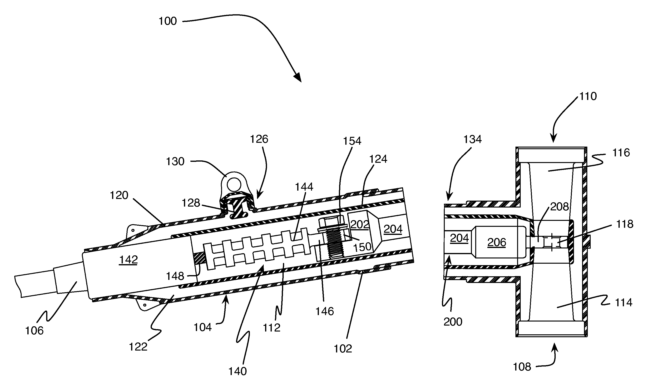
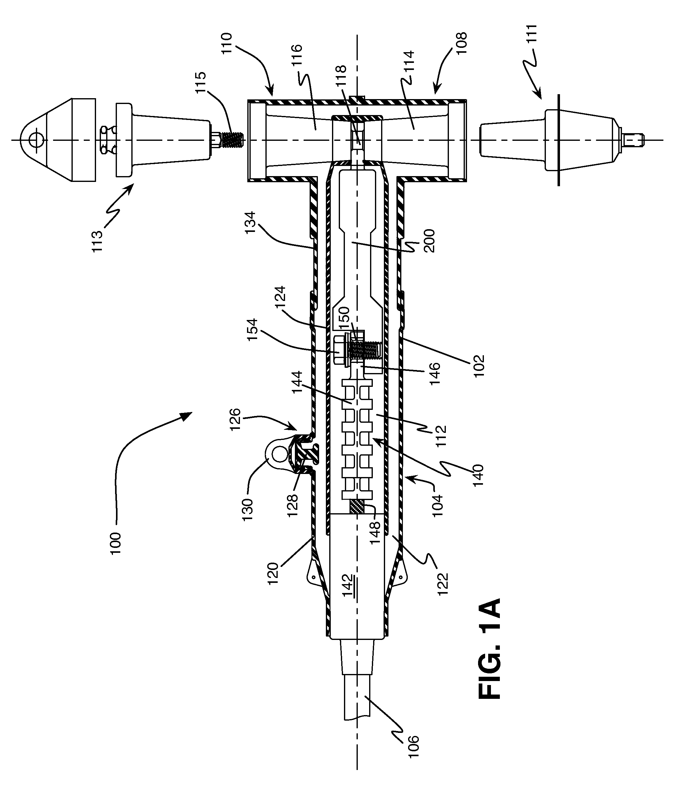
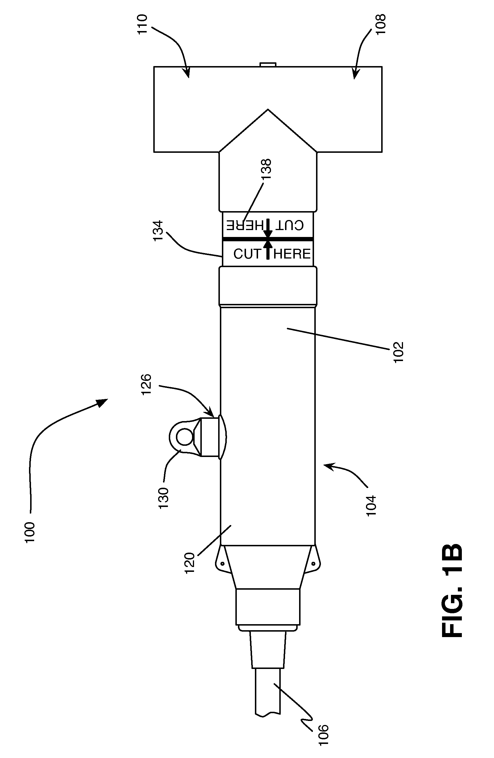
[0010]The following detailed description refers to the accompanying drawings. The same reference numbers in different drawings may identify the same or similar elements.

[0011]One or more embodiments disclosed herein relate to a power cable connector, such as an elbow or T-connector having a sacrificial component. More specifically, the connector may include a power cable receiving body and at least one T-end projecting substantially perpendicularly from the receiving body. The power cable receiving portion is configured to receive a power cable and the T-end is configured to receive an equipment bushing. The power cable operates by enabling current to flow between the bushing and the cable.

[0012]Power cables for use with the described embodiments include a terminating component, such as a spade connector affixed to a free end thereof. In normal operation, the end of the spade connector projects through the power cable receiving body into proximal relationship with the bushing positi...


PUM

PropertyMeasurementUnit
voltageaaaaaaaaaa
voltageaaaaaaaaaa
voltagesaaaaaaaaaa

Abstract

An electrical connector assembly includes a housing body that includes a cable receiving end having a first bore extending therethrough and at least one equipment end projecting perpendicular to the cable receiving end. The at least one equipment end includes a second bore extending therethrough that communicates with the first bore in the cable receiving end. A sacrificial bar is configured to be received within the cable receiving end and includes a first end for coupling to an end of a prepared electrical power cable and a second end configured to project into the second bore and conductively couple with an electrical device received within the at least one equipment end. The housing body and sacrificial bar are configured to be cut through to confirm that the electrical connector is de-energized.

Description

CROSS-REFERENCE TO RELATED APPLICATION[0001]This application is a non-provisional of U.S. Provisional Patent Application No. 61 / 558,204 filed on Nov. 10, 2011, the entirety of which is hereby incorporated by reference herein.BACKGROUND OF THE INVENTION[0002]The present invention relates to electrical cable connectors, such as splicing connectors for joining two or more electrical cables, loadbreak connectors, and deadbreak connectors. More particularly, aspects described herein relate to an electrical cable connector that includes a feature for enabling personnel to confirm that the connector is de-energized.[0003]High and medium voltage electrical connectors and components typically operate in the 15 to 35 kilovolt (kV) range. Because such voltages are potentially very dangerous, it is typically necessary for personnel to confirm that the power is disconnected before commencing work or repair. Known methods of visual or physical de-energizing confirmation include “spiking the cable...

Claims


Application Information

Patent Timeline
Patent Type & Authority Patents(United States)
IPC IPC(8): H01R13/53
CPCH01R43/002H01R13/53Y10T29/49117
Inventor SIEBENS, LARRY N.
Owner THOMAS & BETTS INT INC
Why Eureka
Try Eureka