Apparatus and method for producing light-responsive surfaces on opaque materials

a technology of opaque materials and apparatus, applied in dough shaping and cutting apparatus, digital data processing details, forming/stuttering elements, etc., can solve the problem that the type of ridge is unsuitable for producing anything but the simplest motifs, and achieve the effect of clearer images, and increasing or decreasing the contrast of images

Active Publication Date: 2013-06-04
LEMAIRE ALEXANDER B
View PDF52 Cites 6 Cited by
  • Summary
  • Abstract
  • Description
  • Claims
  • Application Information

AI Technical Summary

Benefits of technology

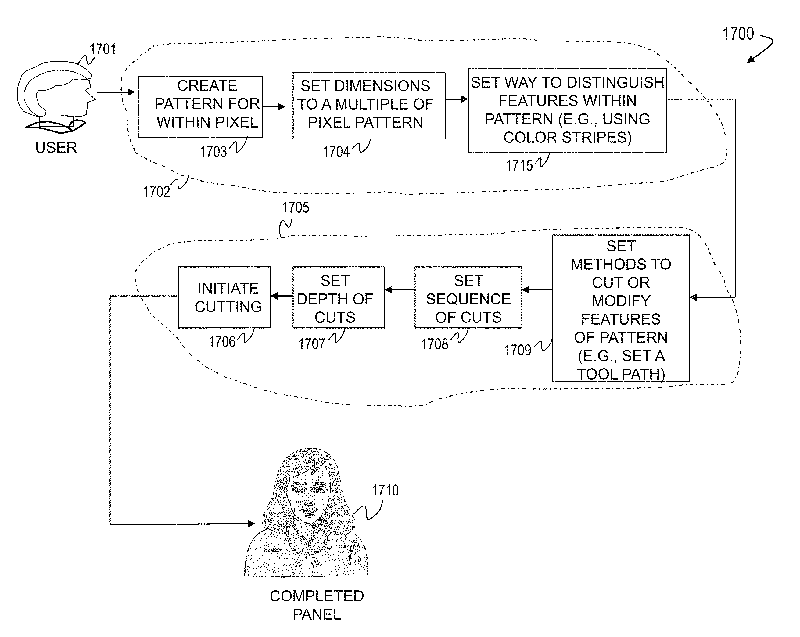
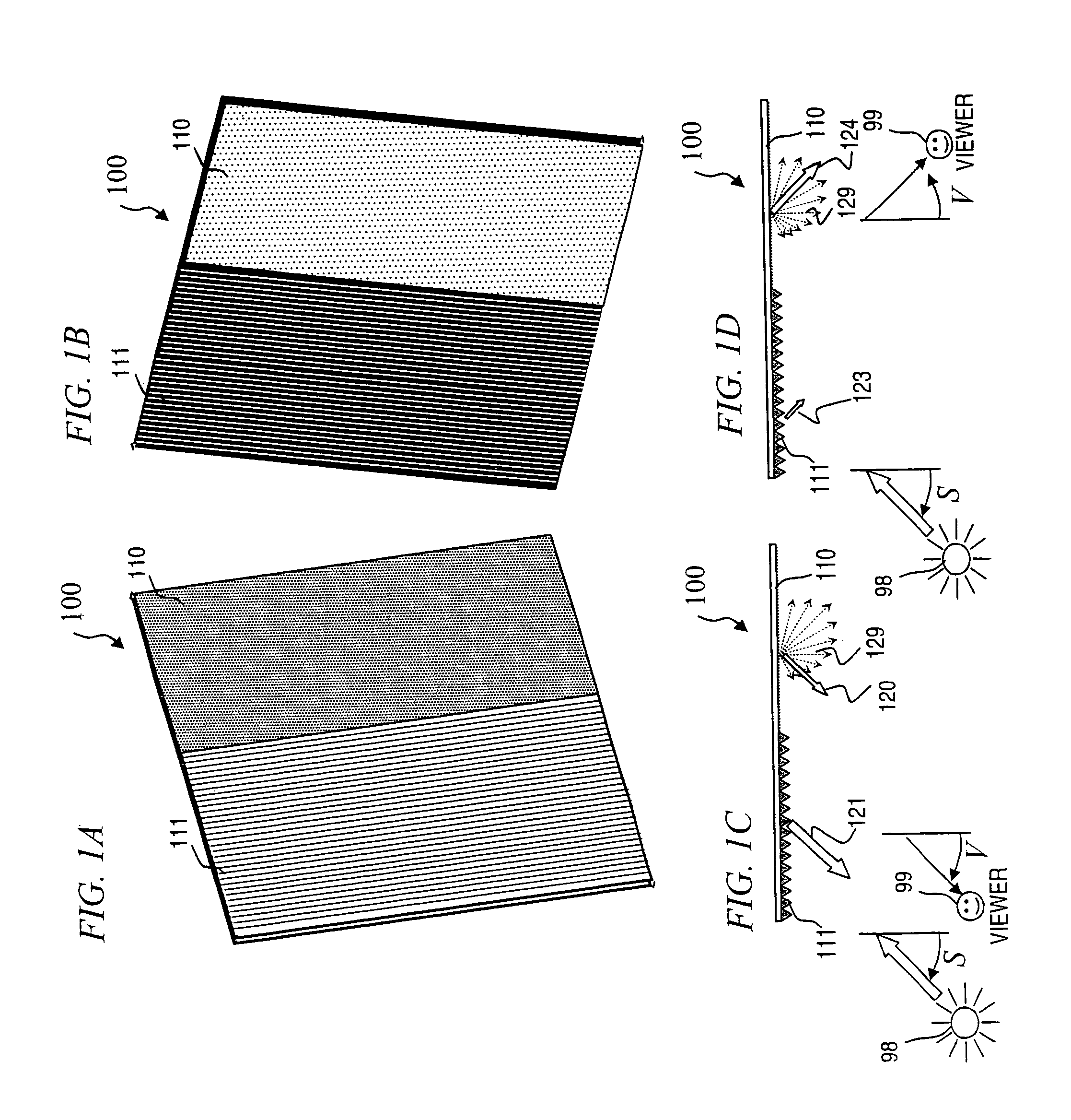
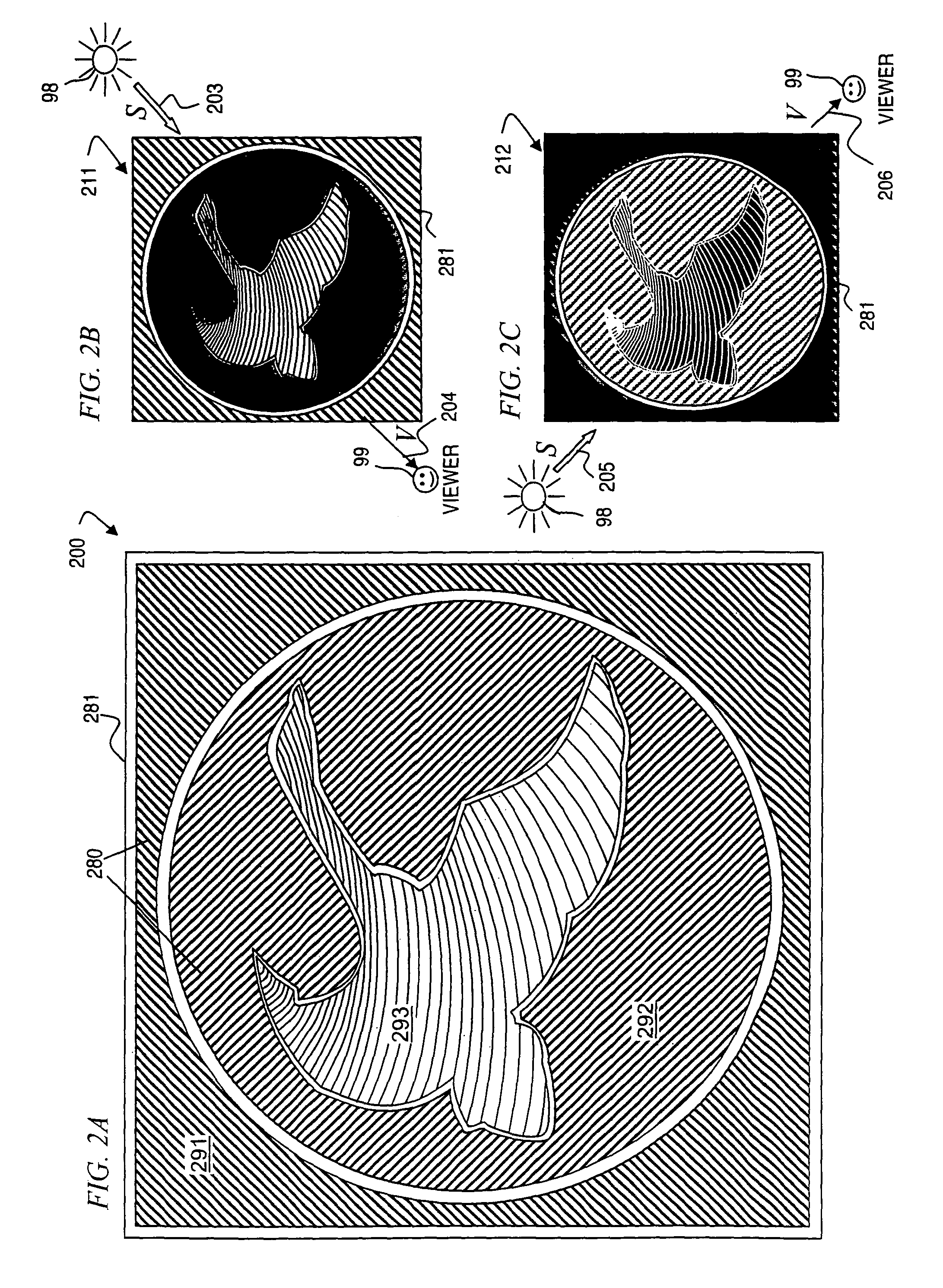
[0006]In some embodiments, the present invention uses grooves and ridges that come to a point to give definition between light and shade and produce the desired imagery solely from light and shade produced by the specific angles of the grooves and ridges on an overall surface relative to the angle of illumination to a source of light, such as the sun, and the angle of viewing to a viewer. Unlike previous grooved surfaces, the surfaces of the present invention use the givens (independent variables) of illumination angle and viewing angle along with the desired relative brightness for each one of a plurality of areas on a surface to calculate or determine the directions of the ridges that cover each respective area. The resulting ridge-direction specifications that are calculated are used to create a surface (e.g., a map that can be used to manually carve the ridge pattern in a block of architectural foam, or that can be used to direct a CNC machine to move a router that mills the parallel grooves to form the ridge pattern in a sheet of medium-density fiberboard (MDF), aluminum, or other suitable material). The resulting surface can be used directly as the surface to be viewed, or can be used as a negative mold on which to cast a plurality of positive replica surfaces to be viewed, or as a positive master on which to cast a plurality of negative mold surfaces, which are then each used to cast a plurality of positive replica surfaces to be viewed. In some embodiments, the surfaces to be viewed are of an opaque material and have a dull or diffusing surface. Because the relative brightnesses (of each area having different ridge-direction angles) change differently as the illumination angle and / or viewing angle changes (i.e., some areas can become relatively brighter to the viewer, while other areas simultaneously become darker), the surfaces being viewed appear lustrous, particularly as viewed from afar while illumination angle and / or viewing angle changes relatively quickly.
[0007]When the illumination angle is from any angle except directly perpendicular to the overall surface and / or the viewing angle is from any angle except directly perpendicular to the overall surface, the light will be separated, with one side of the groove being brighter and the other less bright or in shade. Some embodiments use grooves on some areas of the surface, with a flat frontal surface on other areas, in order to direct or focus the viewer's attention to the grooved portions (which will appear lustrous, with light / dark patterns that change as viewing angle changes). The use of pointed ridges alone, even on a flat surface, arranged in angular sequence (i.e., where the directions of the lines formed by the ridges change over different areas of the surface), can be used to produce changing areas of light and shade normally seen in only in three-dimensional objects or in much more complex surface structures (such as well varnished wood veneers). Additionally, these arranged grooves will give selective (and predetermined) change in brightness, causing areas of the image to change in a manner emulating what is normally considered a lustrous or shiny surface even in totally opaque surfaces, such as carved stone or cast concrete. When viewed frontally (i.e., perpendicular to the overall surface), with frontal lighting (i.e., illumination also perpendicular to the overall surface, or with very diffuse light such as outdoors on a cloudy day), no shadows are produced and all the grooves and ridges are fully illuminated and observed, creating no image since all areas reflect substantially the same amount of light. When the lighting changes to become increasingly angled, shadows begin to appear (even when viewed frontally), and the lighting on different sides of the groove begins to differentiate (the side of the ridge towards the light becoming brighter and the side away from the light becoming darker), causing the image to emerge. When viewed at angles moving away from perpendicular, some of the grooves begin to be partially obscured, and in this manner the contrast of image can increase or decrease. The greater the angle of lighting relative to the vector perpendicular to the surface, or the more acute the viewing angle, the higher the contrast or clearer the image. In some embodiments, the size of the ridge or width and depth of the groove is relatively unimportant in this process, and may be made small enough that, when viewed from the typical viewing distance, the ridge is unseen, and only the various levels of light and shade are perceived. In some embodiments, the different ridge-direction angles are used to create half-tone images (similar to traditional newspaper images, wherein each pixel includes a black spot on a white background, and varying the size of the black spot (i.e., changing the ratio of black to white in each pixel) produces a gray-scale level for each of the pixels that, when viewed from a distance, provides a pleasing gray-scale image.
[0008]In some embodiments, the present invention provides a method for forming a lustrous, light-reflecting design or pattern composed of ridges and valleys, where on different areas of the surface, different ridge-direction angles produce eerily changing light patterns into a uniformly-colored opaque material. This pattern will create the appearance based on the perspective of the viewer, the position of the light source, the different ridge-direction angles, and sidewall angle and depth of the grooves of a design created from light and shadows on the illuminated grooves.

Problems solved by technology

Such grooves or ridges normally have a flat frontal surface which causes the shadow portions generated to be a minor component of the design, and this type of ridge is unsuitable for producing anything but the simplest motifs.
In these decorative uses, the grooves or ridges are part of the composition, and do not serve to produce a complete image by differences in light and shade.

Method used


Image

  • Apparatus and method for producing light-responsive surfaces on opaque materials
  • Apparatus and method for producing light-responsive surfaces on opaque materials
  • Apparatus and method for producing light-responsive surfaces on opaque materials

Examples


Embodiment Construction

[0073]In the following detailed description of the preferred embodiments, reference is made to the accompanying drawings that form a part hereof, and in which are shown by way of illustration specific embodiments in which the invention may be practiced. It is understood that other embodiments may be utilized and structural changes may be made without departing from the scope of the present invention.

[0074]The leading digit(s) of reference numbers appearing in the Figures generally corresponds to the Figure number in which that component is first introduced, such that the same reference number is used throughout to refer to an identical component that appears in multiple Figures. Signals and connections may be referred to by the same reference number or label, and the actual meaning will be clear from its use in the context of the description.

[0075]Examples of Various Light-Responsive, Lustrous Surfaces

[0076]In some embodiments, the present invention provides an impressive, durable l...


PUM

PropertyMeasurementUnit
groove wall anglesaaaaaaaaaa
wall anglesaaaaaaaaaa
groove wall anglesaaaaaaaaaa

Abstract

The present invention provides for a method of creating a lustrous surface in opaque materials using ridge angles, and valleys of varying depths cut, imprinted or pressed into the opaque material. The combination of the light reflecting ridges, angles to reflect more or less light, and a shadow effect arising from a combination of the valley depths and the angle of the ridges allows one to use light and shadow to create a pattern or series of patterns in the opaque materials. These patterns are created using a process whereby a design is first created, then cut into a master blank using some type of manual or computer-aided method. Next, this pattern is inlaid, pressed, or imprinted into a blank panel composed of the opaque material. In some embodiments, this opaque material is allowed to set, thus creating a finished article of manufacture in the form of a panel.

Description

CROSS REFERENCE TO RELATED APPLICATIONS[0001]This application claims priority under 35 USC §119(e) to U.S. Provisional Patent Application No. 60 / 701,856 filed Jul. 21, 2005 and which is incorporated by reference in its entirety herein. Additionally, this application is related to U.S. patent application Ser. Nos. 10 / 900,831, filed Jul. 28, 2004 (now U.S. Pat. 8,365,491 on Feb. 5, 2013), and 10 / 410,060, filed Apr. 9, 2003 (now abandoned), both of which are titled “PARQUET PANEL COVERING”, and both of which are incorporated by reference in their entirety herein.FIELD OF THE INVENTIONS[0002]This invention relates to the field of an apparatus, method, and article of manufacture for embedding a lustrous, light-reflecting (having varying amounts of illumination to the viewer) pattern into an opaque material using ridges set at a plurality of different angles, and / or valleys of differing depths or side-wall slopes, optionally set into a master and operable for forming a molded product usin...

Claims


Application Information

Patent Timeline
Patent Type & Authority Patents(United States)
IPC IPC(8): B32B33/00
CPCB44C5/04B44F1/02E04F13/0871E04G9/10G02B5/021G02B5/0221G02B5/0284G02B5/045G09F19/22G05B19/04G02B26/02
Inventor SCHRUNK, THOMAS R.
Owner LEMAIRE ALEXANDER B
Why Eureka
Try Eureka