
Voice coil motor

a voice coil motor and motor body technology, applied in the field can solve the problems of difficult to precisely drive the lens, the manufacturing tolerances of voice coil motors cannot help being accumulated, and the inability to control the distance between the image sensor and the lens adjusting the magnification and focus, etc., to achieve the effect of reducing the total tolerance generated by accumulation of manufacturing tolerances of each component for driving the lens

Active Publication Date: 2013-06-04
LG INNOTEK CO LTD
View PDF8 Cites 6 Cited by
  • Summary
  • Abstract
  • Description
  • Claims
  • Application Information

AI Technical Summary

Benefits of technology

The invention is about a voice coil motor that reduces the chances of damage or breakage due to external shocks or vibrations. It achieves this by minimizing the overall tolerances of the components used to drive the lens, which would otherwise accumulate during manufacturing. This results in a more reliable and durable motor that can withstand external shocks and vibrations.

Problems solved by technology

It was impossible to control a distance between an image sensor and a lens adjusting a magnification and a focus.
Generally, the voice coil motor is constituted of many components such as a mover, a spacer, and a case, for example, where each component has a manufacturing tolerance since each component is manufactured by each injection molding process or each press process, and therefore, after completion of assembling of all components, the tolerances of the components could not help being accumulated.
The accumulated tolerances caused the voice coil motor to raise a problem hard to precisely drive the lens.
Accordingly, the voice coil motor had a problem in that its drive operates poorly due to the accumulated tolerances.
The voice coil motor had another problem in that the components constructing a voice coil motor are broken or damaged by shocks and / or vibrations transmitted to the spacer, the mover, the stator and the lens through the case from the exterior.

Method used


Image

  • Voice coil motor
  • Voice coil motor

Examples


Embodiment Construction

[0012]Hereinafter, an embodiment in accordance with the present invention will be explained in detail with reference to the accompanying drawings. In the description, the size or the shape of the components shown in the drawings may be exaggeratedly represented. Further, terms defined specifically in consideration of a construction and an operation of the embodiment of the present invention may be different according to an intention or a usual practice of user or operator. The definition to the terms should be derived on the basis of the descriptions throughout the specification.

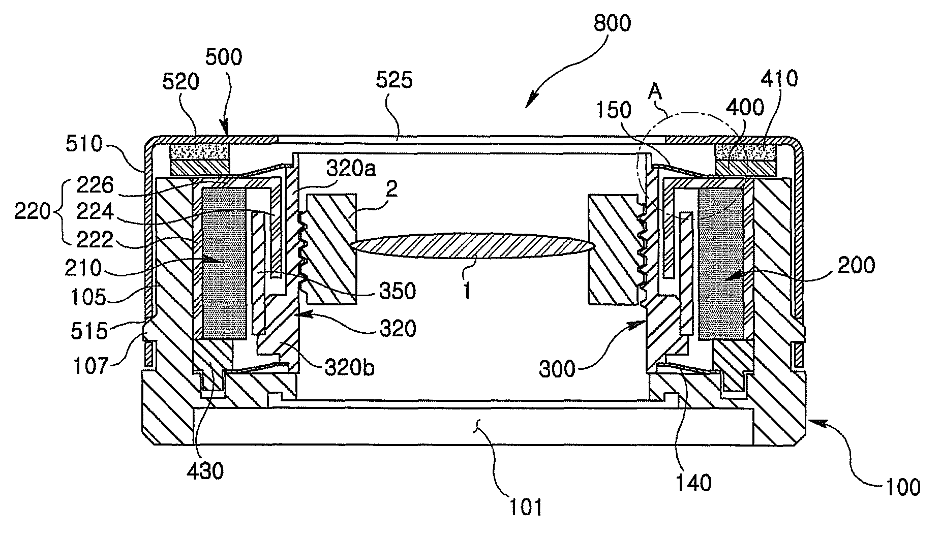
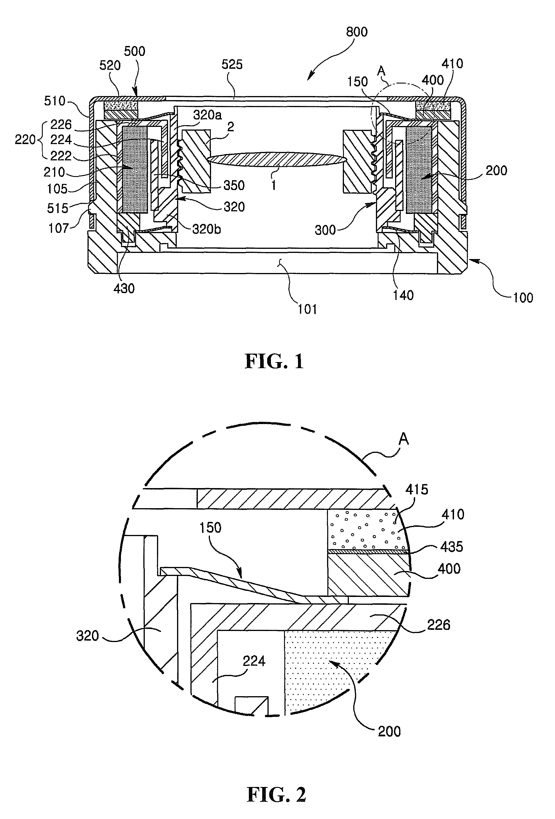
[0013]FIG. 1 is a sectional view of a voice coil motor in accordance with the present invention, and FIG. 2 is an enlarged view of “A” portion circled by dots and lines in FIG. 1.

[0014]Referring to FIGS. 1 and 2, the voice coil motor 800 includes a base 100, a stator 200, a mover 300, a spacer including a first spacer 400 and a second spacer 410, and a case 500. In addition, the voice coil motor 800 may incl...


PUM


Abstract

Disclosed is a voice coil motor, including a base having an opening, a stator is disposed on the base and including a magnet, a mover including a conductive coil opposing with the magnet, and a cylindrical bobbin in which a conductive coil is installed, a case fixed on the base and covering the stator, and a spacer intervened between the stator and the case and constituted with at least two spacers, each formed with different materials to absorb pressures and shocks transmitted to the stator from external.

Description

CROSS-REFERENCE TO RELATED APPLICATION[0001]This application claims the benefit under 35 U.S.C. §119 of Korean Application No. 10-2010-0000462, filed on Jan. 5, 2010, which is hereby incorporated by reference in its entirety.BACKGROUND OF THE DISCLOSURE[0002]1. Field of the Invention[0003]This invention relates to a voice coil motor.[0004]2. Discussion of the Related Art[0005]Recently, various optical apparatuses have been developed, for example, a mobile phone with a built-in micro camera and a high resolution digital camera.[0006]In case of the micro digital camera adopted to the mobile phone. It was impossible to control a distance between an image sensor and a lens adjusting a magnification and a focus. However, owing to such developments of the lens drive apparatus as the voice coil motor, the distance between the image sensor and the lens could be controlled. In particular, the voice coil motor could control the distance between the image sensor and the lens using a gravitatio...

Claims


Application Information

Patent Timeline
Patent Type & Authority Patents(United States)
IPC IPC(8): H02K41/03H02K33/00
CPCH02K41/0356G02B7/04G03B3/02G03B2205/0069H04N23/54H04N23/55
Inventor KWON, YOUNGJU
Owner LG INNOTEK CO LTD
Learn More