Reliable easy-to-maintain economic junction box

An easy-to-maintain, junction box technology, applied in the direction of connection, connecting device parts, electrical components, etc., can solve problems such as difficulty in ensuring the installation of diodes in place, easy-to-damage clips when removing diodes, and lack of particularly good design solutions. The effect of strong line reliability, easy replacement and simple structure

Active Publication Date: 2018-03-09
浙江鑫辉光伏科技有限公司
View PDF7 Cites 2 Cited by
  • Summary
  • Abstract
  • Description
  • Claims
  • Application Information

AI Technical Summary

Problems solved by technology

The traditional junction box does not have a particularly good design scheme for the waterproof sealing of the cable inlet. There are many unreasonable structures in the structure, and the waterproof effect is generally not good.
[0004] The diode in the traditional junction box is generally fixedly connected to the terminal piece through the cage clip, and a supporting part is needed to assist in the assembly of the diode, resulting in a more complicated structure and higher cost
Due to

Method used


Image

  • Reliable easy-to-maintain economic junction box
  • Reliable easy-to-maintain economic junction box
  • Reliable easy-to-maintain economic junction box

Examples


Embodiment 1

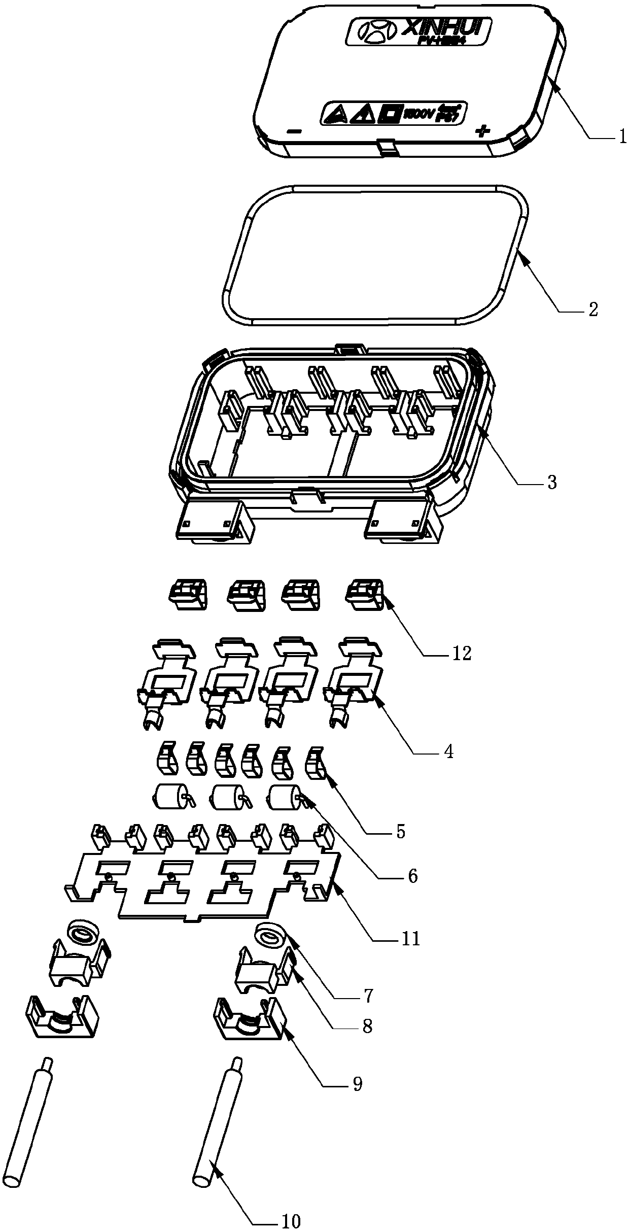
[0044] Such as Figure 6 As shown, the base 3 is a base for installing the cable sealing ring 7 , the sealing pressing block 8 and the wire pressing block 9 . The cable entrance of the base 3 is provided with a sealing pressing block mounting seat 3-7 and a wire pressing block mounting seat 3-8, and the two are connected as one. A wire insertion hole 3-9 is provided in the middle of the sealing briquetting mounting seat 3-7, and the inwall of the wire insertion hole 3-9 is provided with a ring sealing ring placement groove 3-10, and the both sides of the wire insertion hole 3-9 are provided with two A block 3-11, in this embodiment, the specific structure of the block 3-11 is a fixed sealing block hook formed by the outer side of the back of the groove after the sealing block mounting seat 3-7 is grooved. buckle (see Figure 14 ). Two slots 3-12 are arranged on both sides of the wire crimping block mounting base 3-8.

[0045] Such as Figure 7 As shown, the sealing pressi...

Embodiment 2

[0051] refer to Figure 18 , combined with Figure 19 ~ Figure 23 , the base 3 is provided with a wire insertion hole 3-9, and the sealing pressure block 8 is also provided with a wire insertion hole 8-3 of the same size. Close to the rear of the wire insertion hole 8-3 of the sealing pressing block 8, such as Figure 19 shown. Then put the sealing briquetting block 8 with the cable sealing ring 7 installed into the base 3. At this time, the other end surface of the cable sealing ring 7 is close to the wire insertion hole 3-9 of the base 3, and the cable is sealed. Ring 7 communicates with the wire insertion hole 8-3 on the sealing pressing block 8 and the wire insertion hole 3-9 on the base 3, as Figure 20 shown. Insert the cable 10 so that it passes through the wire insertion hole 8-3 on the sealing pressing block 8, the cable sealing ring 7, and the wire insertion hole 3-9 on the base 3 in sequence, and then connects with the components in the base 3, such as Figure ...


PUM


Abstract

The invention discloses a reliable easy-to-maintain economic junction box, which comprises a cover, a box body sealing circle, a base, bus bar clips, terminals, diode clips, diodes, a bottom plate, cable sealing circles, sealing pressing blocks, wire pressing blocks and cables, wherein the box body sealing circle is placed in an annular groove at the top part of the base; the edge of the cover isinserted in the annular groove to squeeze the box body sealing circle; a joint mechanism inactive part arranged on the edge of the cover and a joint mechanism active part arranged on the outer wall ofthe annular groove in the base form a joint mechanism; the joint mechanism active parts simultaneously block the box body sealing circle in the annular groove; multiple interference sealing exists among the base, the cables, the cable sealing circles, the sealing pressing blocks and the wire pressing blocks; and warping bosses are arranged on the base or the bottom plate or the terminals below the diode clips and/or the bus bar clips. A more simplified box body structure, higher reliability, better cable waterproof sealing performance and higher-efficiency diode maintenance and mounting can be realized.

Description

technical field [0001] The invention relates to the field of junction box structure design, in particular to a junction box structure that is reliable, easy to maintain and economical. Background technique [0002] The seal between the cover and the base of the traditional junction box is sealed by pressing the rubber box sealing ring between the cover and the base. The rubber box sealing ring is installed in the tank of the cover, and is only stuck by the stopper next to the tank so as not to fall off. The stopper has limited fixing effect on the sealing ring of the box body, and the sealing ring of the box body is easy to fall off; the thickness of the cover where the sealing ring of the box body is located is small, and the strength is low; the rubber box sealing ring needs to be almost as wide as the tank body to Stuck in the tank, the stopper squeezes the rubber box sealing ring, which is easy to deform and age, which affects the life; the rubber box sealing ring also ...

Claims


Application Information

Patent Timeline
IPC IPC(8): H01R13/52H01R13/66
CPCH01R13/5202H01R13/5208H01R13/6641
Inventor 彭祁军李艳群徐林峰叶炳包宇然
Owner 浙江鑫辉光伏科技有限公司
Why Eureka
Try Eureka