Current localization tracker

a tracker and current technology, applied in the field of sensing the position, can solve the problems of inability or desirable real-time three-dimensional imaging

Active Publication Date: 2013-06-04
BIOSENSE WEBSTER INC
View PDF18 Cites 545 Cited by
  • Summary
  • Abstract
  • Description
  • Claims
  • Application Information

AI Technical Summary

Problems solved by technology

In most situations, however, real-time three-dimensional imaging is not possible or desirable.

Method used


Image

  • Current localization tracker
  • Current localization tracker
  • Current localization tracker

Examples


Embodiment Construction

Overview

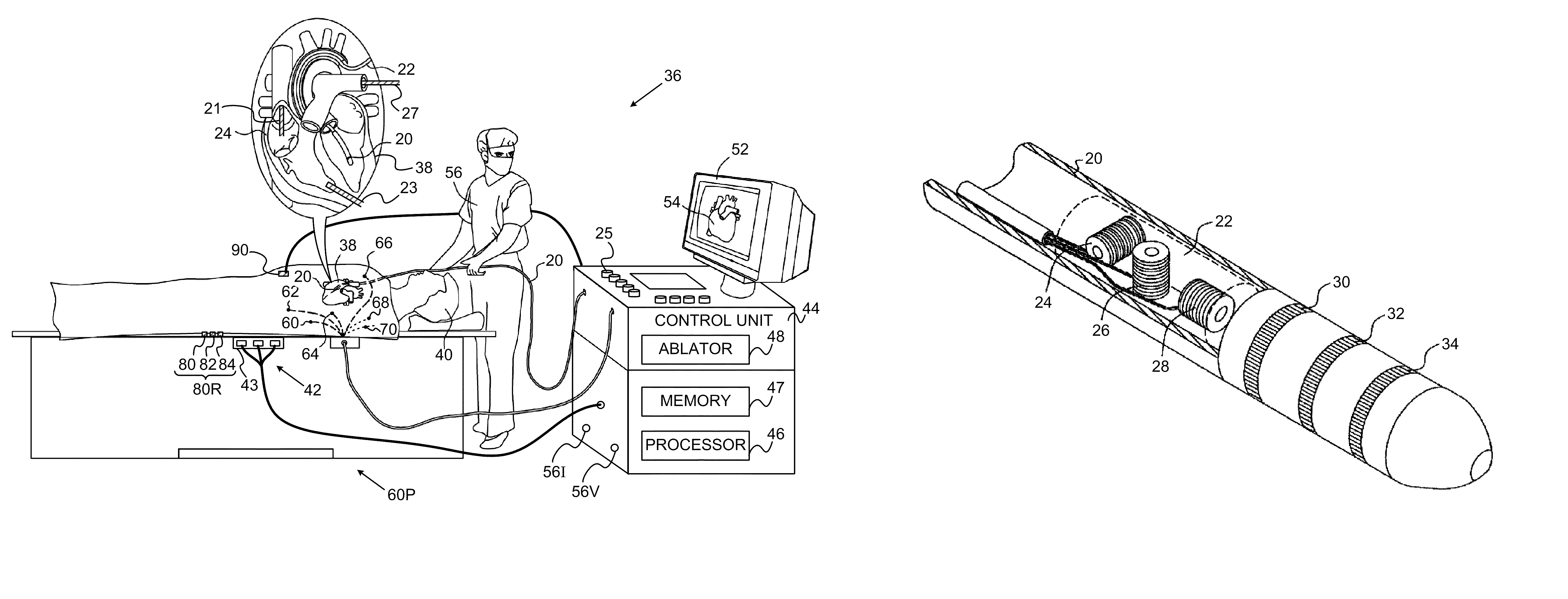
[0078]In embodiments of the present invention, two types of tracking sub-system are used for measuring the location and orientation of an object, herein by way of example assumed to be a catheter tip, within the body of a patient.

[0079]One of the sub-systems, herein termed an advanced current localization (ACL) tracker sub-system, generates a current from an electrode on the catheter tip and measures the current distribution at a number of patches placed on the body surface, and / or at conducting elements positioned within the body. The location of the electrode is calculated from the current distribution.

[0080]The second sub-system may be any tracking system that operates on a different principle to that of the ACL sub-system. The second sub-system typically provides more accurate results than those provided by the ACL sub-system when the latter operates alone. Second sub-systems that may be used include, but are not limited to, imaging systems such as electromagnetic (EM) s...


PUM


Abstract

A method includes positioning body-electrodes in galvanic contact with a body of a patient and positioning a mapping-tool, having a mapping-electrode, in a plurality of regions in the body. The method further includes tracking the mapping-tool at different positions in each of the regions using a location-measuring system, and for each region, generating a respective set of calibration-currents between the body-electrodes and the mapping-electrode at the different positions in the region. A respective relation is derived for each region between the respective set of the calibration-currents and the different positions, and is used in determining the location of an investigation-tool in response to the different respective relations and investigation-tool-currents.

Description

CROSS-REFERENCE TO RELATED APPLICATION[0001]This application claims the benefit of U.S. Provisional Patent Application 61 / 101,308, filed Sep. 30, 2008, which is incorporated herein by reference.FIELD OF THE INVENTION[0002]The present invention relates generally to sensing the position of an object placed within a living body, and specifically to detection and compensation for artifacts experienced during position sensing of a probe in a living body.BACKGROUND OF THE INVENTION[0003]A wide range of medical procedures involve placing objects, such as sensors, tubes, catheters, dispensing devices, and implants, within the body. Real-time imaging methods are often used to assist doctors in visualizing the object and its surroundings during these procedures. In most situations, however, real-time three-dimensional imaging is not possible or desirable. Instead, systems for obtaining real-time spatial coordinates of the internal object are often utilized.[0004]U.S. Patent Application 2007 / 0...

Claims


Application Information

Patent Timeline
Patent Type & Authority Patents(United States)
IPC IPC(8): G01R27/08A61B5/296
CPCA61B5/042A61B5/053A61B5/06A61B5/7207A61B2019/5246A61B2019/5253A61B2034/2046A61B2034/2053A61B5/062A61B5/283
Inventor BAR-TAL, MEIROSADCHY, DANIEL
Owner BIOSENSE WEBSTER INC
Why Eureka
Try Eureka