Objective perceptual video quality evaluation apparatus

a video quality and perception technology, applied in the field of subjective perception video quality evaluation apparatus, can solve problems such as difficult evaluation and television image evaluation methods

Inactive Publication Date: 2013-06-04
KDDI CORP
View PDF4 Cites 0 Cited by
  • Summary
  • Abstract
  • Description
  • Claims
  • Application Information

AI Technical Summary

Benefits of technology

[0011]It is an object of the present invention to provide an objective perceptual video quality evaluation apparatus capable of automatically and objectively evaluating quality of a video intended at a multimedia application or the like without relying on subjective human judgment.
[0013]According to the present invention, the block distortion degree of the evaluated video relative to the original video, the PSNR overall temporal fluctuation degree, and the PSNR local temporal fluctuation degree are extracted as feature amounts. The objective video quality index is calculated based on the feature amounts and is corrected for every frame of the evaluated video, then the evaluation value reflecting the characteristic of the low frame rate video is derived. Therefore, it is possible to realize highly accurate and automatic evaluation of the video qualities of multimedia videos at low resolution and low frame rate, which evaluation has been difficult to make by the conventional television image evaluation method.

Problems solved by technology

Therefore, it is possible to realize highly accurate and automatic evaluation of the video qualities of multimedia videos at low resolution and low frame rate, which evaluation has been difficult to make by the conventional television image evaluation method.

Method used


Image

  • Objective perceptual video quality evaluation apparatus
  • Objective perceptual video quality evaluation apparatus
  • Objective perceptual video quality evaluation apparatus

Examples


Embodiment Construction

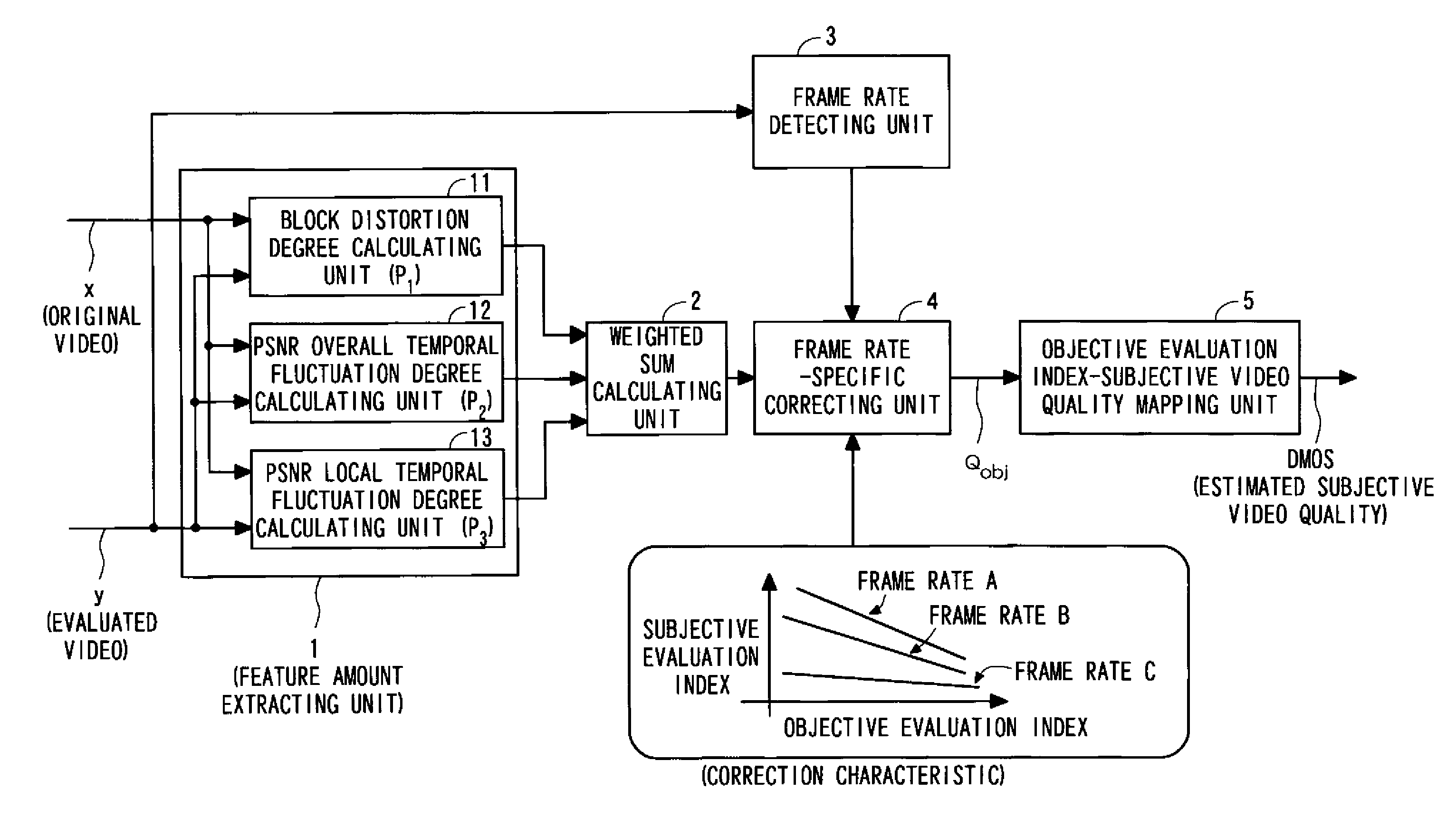
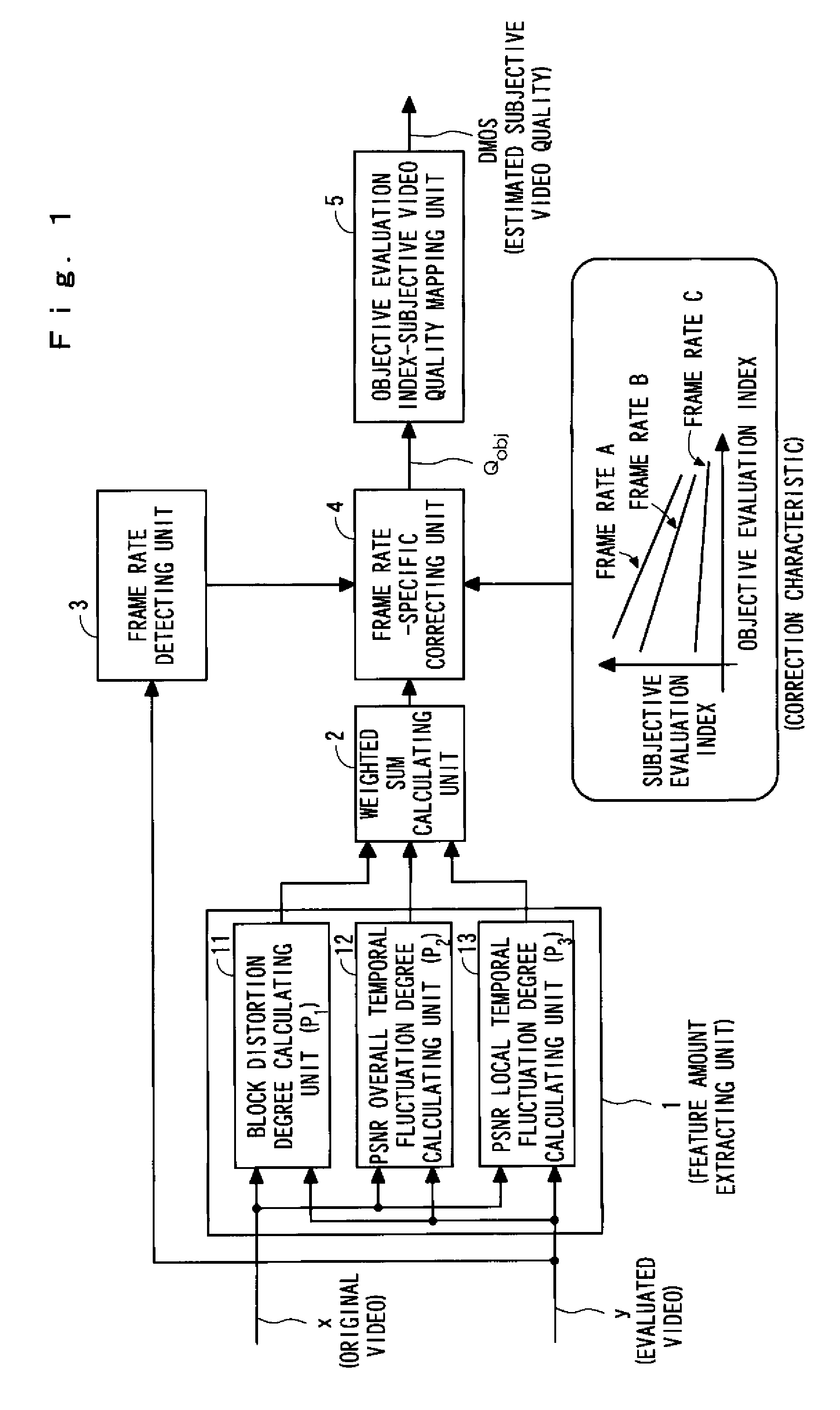
[0025]Preferred embodiments of the present invention will be described hereinafter in detail with reference to the accompanying drawings. FIG. 1 is a block diagram of an automatic objective perceptual video quality evaluation apparatus according to an embodiment of the present invention. The automatic objective perceptual video quality evaluation apparatus receives two types of video signals, and analyzing the video signals, thereby finally outputting a subjective video quality estimated value. Meanwhile, an image corresponding to a video signal before being subjected to video-transmission-related image processing is denoted by “original video x”, and an image corresponding to a received transmission image and to be subjected to evaluation of a subjective quality according to the present invention is denoted by “evaluated video y”.

[0026]As shown in FIG. 1, the automatic objective perceptual video quality evaluation apparatus according to the embodiment comprises computer based digit...


PUM


Abstract

A feature amount extracting unit extracts a block distortion degree of an evaluated video y relative to an original video x, a PSNR overall temporal fluctuation degree, and a PSNR local temporal fluctuation degree as feature amounts. A weighted sum calculating unit calculates a weighted sum of these feature amounts, and calculates an objective video quality index. Frame rate detecting unit detects frame rate of the evaluated video y. A correcting unit corrects the objective video quality index based on the frame rate detected by the frame rate detecting unit. An objective evaluation index-subjective video quality mapping unit applies the corrected objective video quality index Qobj to a correlation between an objective video quality index and a subjective video quality given in advance, thereby deriving a subjective video quality estimated value DMOS.

Description

BACKGROUND OF THE INVENTION[0001]1. Field of the Invention[0002]The present invention relates to an objective perceptual video quality evaluation apparatus for automatically evaluating quality of a video, e.g., a received video image or a reproduced video image which is transmitted or accumulated after being subjected to an image processing such as compression coding without relying on subjective human judgment.[0003]2. Description of the Related Art[0004]There are conventionally known techniques related to the present invention as disclosed in, for example, ITU-T Recommendation J.143, “User requirements for objective perceptual video quality measurements in digital cable television” and ITU-T Recommendation J.144, “Objective perceptual video quality measurement techniques for digital cable television in the presence of a full reference”.[0005]The ITU-T Recommendation J.143 mainly describes user requirements for automatic objective perceptual video quality measurements in television...

Claims


Application Information

Patent Timeline
Patent Type & Authority Patents(United States)
IPC IPC(8): H04N7/12H04N11/04H04N11/02H04N17/04H04N19/00H04N19/136
CPCH04N19/176H04N19/61H04N19/587H04N19/154H04N19/132
Inventor SUGIMOTO, OSAMUSAKAZAWA, SHIGEYUKIKOIKE, ATSUSHI
Owner KDDI CORP
Why Eureka
Try Eureka