
Straight edge circle tool

a straight edge circle and tool technology, applied in the field of construction tools, can solve the problems of tool loss, more difficulty, and difficulty in forming precise curves, and achieve the effects of convenient use, reduced cost, and improved accuracy

Inactive Publication Date: 2013-06-11
APLIN PHILIP CYRIL +1
View PDF12 Cites 4 Cited by
  • Summary
  • Abstract
  • Description
  • Claims
  • Application Information

AI Technical Summary

Benefits of technology

The present invention is a marking tool that can be used for forming precise curves in construction. The tool has a series of holes, including one at each extreme end and one at each zero point. The tool can be easily hung from a wall and is designed to maintain its form and not break out of an end of the tool. The tool can be used for marking both straight edge lines and curving line segments. It is easy to use and performs precise marking, especially of curves. The tool can be made from relatively low cost materials and is of rigid form.

Problems solved by technology

However, when larger curves need to be formed on a piece of material before it is cut, more difficulty is experienced.
Also, when laying out forms, such as for concrete pouring and when building landscaping hardscape elements, when a larger curve needs to be laid out during a construction process, it can be difficult to form precise curves.
Construction tools need to be simple to use or their propensity for non-use or misuse is sufficiently great that the tool loses its usefulness.

Method used


Image

  • Straight edge circle tool
  • Straight edge circle tool
  • Straight edge circle tool

Examples


Embodiment Construction

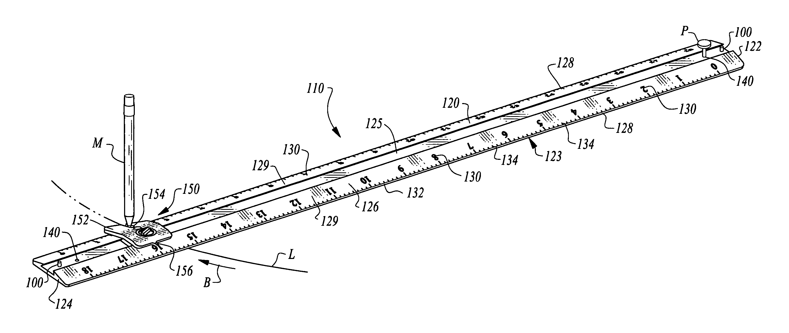
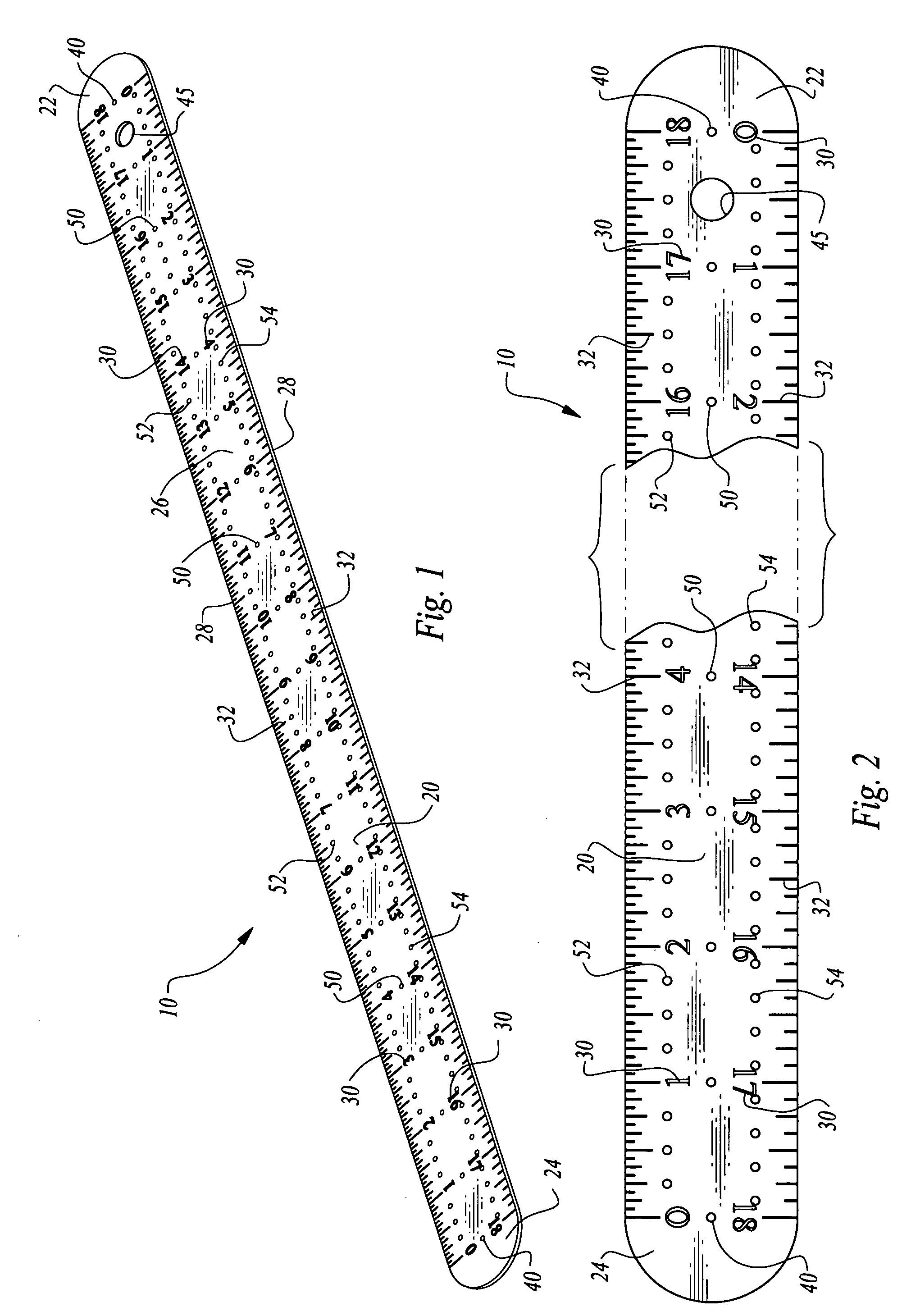
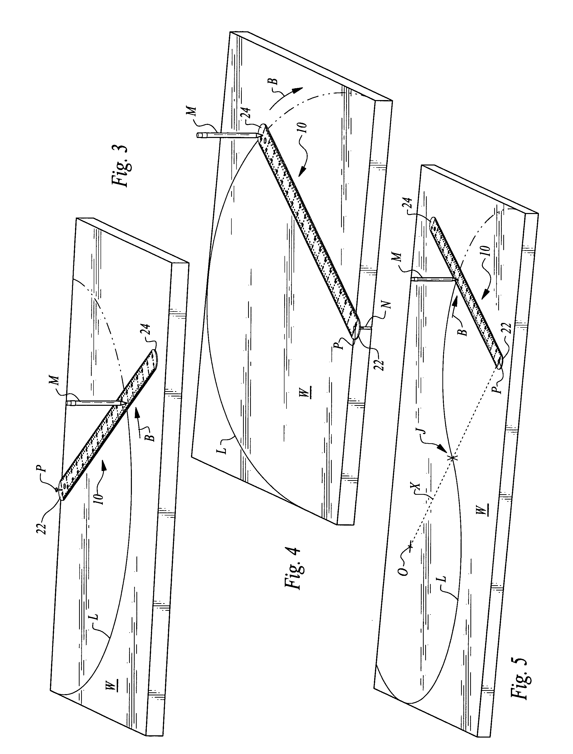
[0034]Referring to the drawings, wherein like reference numerals represent like parts throughout the various drawing figures, reference numeral 10 is directed to a tool for use in forming a line L (FIGS. 3-5) having a curving contour or a line L which is straight. The tool 10 can be used to form curving lines L having a variety of different distances from an origin O point (FIG. 5) such as for use in forming curving structures within a building or landscape.

[0035]In essence, and with particular reference to FIGS. 1 and 2, basic details of the tool 10 of this invention are described as exhibited in a preferred embodiment. In this embodiment, an eighteen inch tool 10 is depicted, while tools having greater (or lesser) lengths could also be provided. The tool 10 is formed of an elongate rigid bar 20 with straight side edges 28 extending between opposite ends 22, 24. Indicia 30, typically in the form of numbers, are provided on the bar 20, indicative of a distance from a center hole 40 ...


PUM


Abstract

The tool is formed of an elongate rigid bar having a pair of straight side edges extending between opposite ends. Indicia are provided adjacent graduations correlating with distances away from center holes located at each end of the bar. A series of marking holes are provided at various distances away from the center holes. Thus, when a pin is provided through one center hole, a marking tool can be placed within a marking hole having a distance corresponding with a radius of a curve to be formed, and the bar can be rotated about the pin in the center hole while the marker is allowed to form a mark in an underlying workpiece. The straight edges of the tool can also be utilized for forming straight edges.

Description

CROSS-REFERENCE TO RELATED APPLICATIONS[0001]This application claims benefit under Title 35, United States Code §119(e) of U.S. Provisional Application No. 61 / 396,811 filed on Jun. 2, 2010.FIELD OF THE INVENTION[0002]The following invention relates to construction tools for forming curves and straight edges. More particularly, this invention relates to construction tools which can mark a workpiece along a curve segment for forming a curve in the workpiece.BACKGROUND OF THE INVENTION[0003]When practicing the construction arts it is often necessary to mark out lines along which different actions are required to be made. For instance, when a large piece of sheet material (i.e. plywood or oriented strand board (OSB)) is to be cut in a particular fashion. When the lines are straight, some form of straight edge tool is typically utilized as is known in the art. When curves are required to be drawn, a compass can be used if the curve is circular and relatively short. However, when larger c...

Claims


Application Information

Patent Timeline
Patent Type & Authority Patents(United States)
IPC IPC(8): B43L9/04
CPCB43L7/005B43L9/007
Inventor APLIN, PHILIP CYRILKUMMLI, PETER
Owner APLIN PHILIP CYRIL
Learn More