Wide range DC power supply with bypassed multiplier circuits

a dc power supply and multiplier circuit technology, applied in the direction of electric variable regulation, process and machine control, instruments, etc., can solve the problems of low impedance arcs that are detrimental, current limitation preventing the power supply from operating over a wide full-power operating voltage range, and limited output current of voltage multipliers, so as to increase the maximum available output current and ensure the effect of high efficiency of the power supply

Active Publication Date: 2013-06-11
COLORADO POWER ELECTRONICS
View PDF6 Cites 5 Cited by
  • Summary
  • Abstract
  • Description
  • Claims
  • Application Information

AI Technical Summary

Benefits of technology

[0004]U.S. Pat. No. 7,477,042 utilizes a set of three voltage multipliers identical to the teachings of U.S. Pat. No. 4,994,953, but it explicitly describes a string of filter capacitors that is shared among the three voltage multipliers. Significant energy is stored in this string of filter capacitors. Plasma loads such as those used in sputtering and electric propulsion can develop low impedance arcs that are detrimental if too much energy is dumped into them. Consequently, power supplies with low stored energy are preferred. The common string of filter capacitors described in these prior art patents can have less capacitance than three separate voltage multipliers with three separate filter capacitor strings due to the reduction of currents flowing in the filter capacitor string at common nodes when the currents from the three phases are combined. What was not recognized in the prior art, however, was that the common string of filter capacitors may be entirely removed, thereby further reducing the stored energy.
[0007]The dc power supply of the present invention provides dc power over a wide range of output voltages at full operating power by utilizing multiplier circuits supplied by a source of high-frequency alternating current. These multiplier circuits include a plurality of multiplier cells, each containing series-connected diodes and a driving capacitor. The multiplier cells are shunted by bypass rectifiers that are arranged to allow current to flow from multiplier input terminals to output terminals of the power supply. The bypass rectifiers do not conduct current for low output current levels, but conduct increasing levels of current when output currents increase beyond a conduction threshold value, thereby increasing the maximum available output current. The multiplier driving capacitors exhibit significant ripple voltages at moderate output currents, and may be completely discharged each cycle at higher output currents. Interactions among the diodes and capacitors in the multiplier circuits cause the amplitude of the alternating currents delivered by the source of high-frequency alternating current to the Multiplier input terminals to remain relatively constant as the output voltage is varied over a wide range while operating at full power. This allows the efficiency of the power supply to remain high over a wide range of output voltages.BRIEF DESCRIPTION OF THE DRAWINGS

Problems solved by technology

U.S. Pat. No. 4,994,953 teaches the use of voltage multipliers to rectify the output voltage of three-phase inverters for space applications, but the output current of voltage multipliers is limited by the driving capacitors that supply the ac current to the rectifier diodes.
The output current limitation prevents the power supply from operating over a wide full-power operating voltage range unless impractically large driving capacitors were used.
Plasma loads such as those used in sputtering and electric propulsion can develop low impedance arcs that are detrimental if too much energy is dumped into them.
What was not recognized in the prior art, however, was that the common string of filter capacitors may be entirely removed, thereby further reducing the stored energy.

Method used


Image

  • Wide range DC power supply with bypassed multiplier circuits
  • Wide range DC power supply with bypassed multiplier circuits
  • Wide range DC power supply with bypassed multiplier circuits

Examples


Embodiment Construction

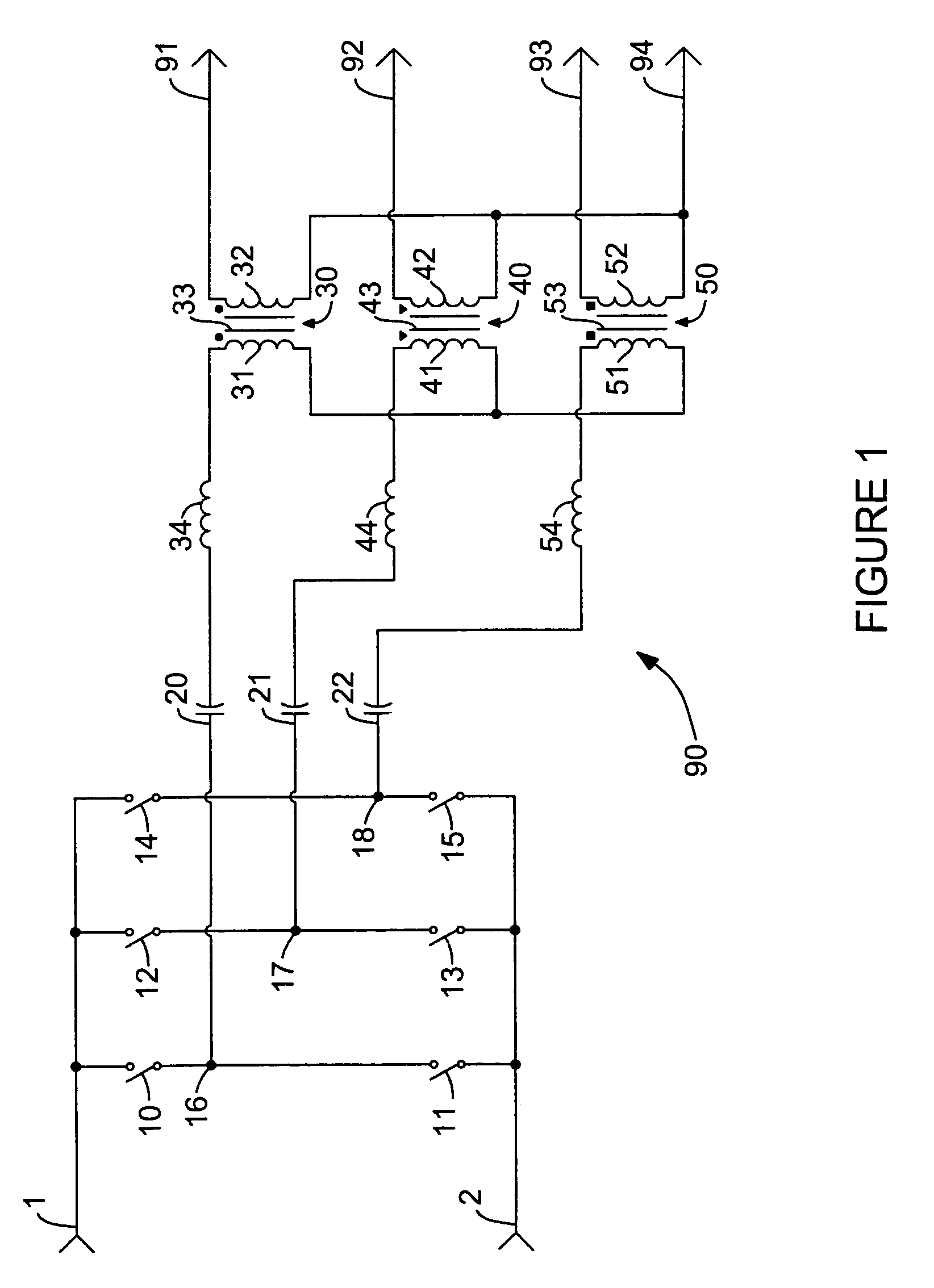
[0014]Referring to FIG. 1, there is shown a prior art three-phase resonant inverter 90 that is representative of one of the many types of inverters that may be employed to provide a source of high-frequency alternating current for use by the power supplies of the present invention. Three-phase resonant inverter 90 receives a conventional source of dc power at input terminals 1 and 2, and provides three phases of square wave voltages at switching output terminals 16, 17, 18 through the actions of switching devices 10-15 which are connected to form a three-phase switching bridge. Each of the switching devices 10-15 includes a conventional electronic switch such as a transistor, and may also include a conventional freewheeling diode, connected in an anti-parallel manner, and a blocking diode in series with the electronic switch. The switching devices 10-15 are operated by a conventional switching controller that is not shown. The controller operates the switches at frequencies that are...


PUM


Abstract

A power supply provides dc power over a wide range of output voltages at full operating power by utilizing multiplying circuits (200) supplied by a source of high-frequency alternating current (90). The multiplier circuits include a plurality of multiplier cells containing at least two diodes (207, 209) and a driving capacitor (208). The multiplier cells are shunted by bypass rectifiers (205, 206) arranged such that currents are allowed to flow from multiplier input terminals to power supply output terminals. The bypass rectifiers do not conduct current for low output current levels, but conduct increasing levels of current when output currents increase beyond a conduction threshold value, thereby increasing the maximum available output current. Interactions among the diodes and capacitors in the multiplier circuits cause the amplitudes of the multiplier input currents to remain relatively constant as the output voltage is varied while operating at full power.

Description

BACKGROUND AND SUMMARY OF THE INVENTION[0001]This invention relates to high voltage power supplies such as those used in plasma sputtering, space electric propulsion, lasers and X-ray machines, as well as to power supplies that have a wide full-power operating range that allows them to provide high current at low output voltages and low current at high output voltages.[0002]U.S. Pat. No. 6,697,265 teaches multiphase L-C-C resonant power supplies for plasma sputtering applications having a wide full-power output voltage range. These power supplies have capacitors in parallel with output rectifier diodes, with at least two diode-capacitor combinations connected in series between the output voltage terminals. The output rectifier circuit shown in FIG. 5 of that patent can produce a maximum dc voltage of twice the peak value of the rectifier ac input voltage. The voltage for the output rectifier is typically supplied from a transformer. In high-voltage power supplies, it can be advantag...

Claims


Application Information

Patent Timeline
Patent Type & Authority Patents(United States)
IPC IPC(8): H02M7/25
CPCH02M3/28H02M7/103
Inventor DRUMMOND, GEOFFREY N.HESTERMAN, BRYCE L.
Owner COLORADO POWER ELECTRONICS
Why Eureka
Try Eureka