
CMOS low voltage high-speed differential amplifier

a high-speed, differential amplifier technology, applied in the field of electromechanical circuits, can solve problems such as limiting the response speed of the amplifier, and achieve the effect of less capacitance and reduced response tim

Inactive Publication Date: 2006-01-24
TWITTER INC
View PDF5 Cites 1 Cited by
  • Summary
  • Abstract
  • Description
  • Claims
  • Application Information

AI Technical Summary

Benefits of technology

[0009]The passive biasing elements, which exhibit less capacitance than the corresponding active elements, reduce the response time associated with the differential amplifier.

Problems solved by technology

However, a typical differential amplifier will operate only over a relatively narrow range of common-mode input voltages.
Certain transistors employed in a device according to the Bazes patent exhibit capacitance, which limits the response speed of the amplifier.

Method used


Image

  • CMOS low voltage high-speed differential amplifier
  • CMOS low voltage high-speed differential amplifier
  • CMOS low voltage high-speed differential amplifier

Examples


Embodiment Construction

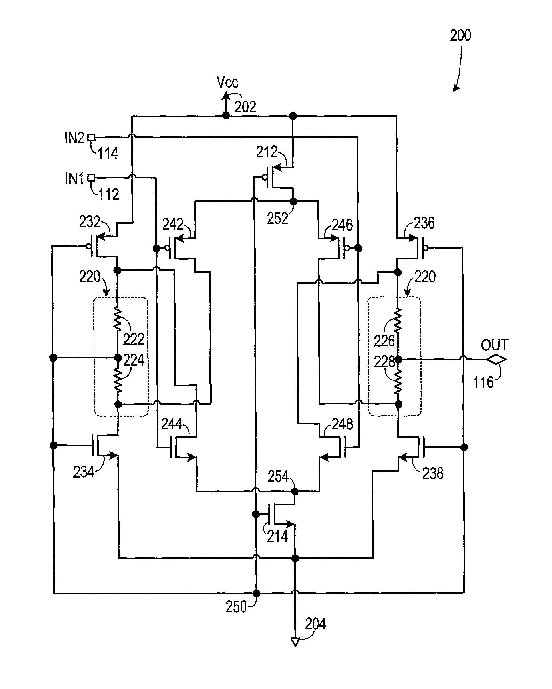
[0013]A preferred embodiment of the invention is now described in detail. Referring to the drawings, like numbers indicate like parts throughout the views. As used in the description herein and throughout the claims, the following terms take the meanings explicitly associated herein, unless the context clearly dictates otherwise: the meaning of “a,”“an,” and “the” includes plural reference, the meaning of “in” includes “in” and “on.”

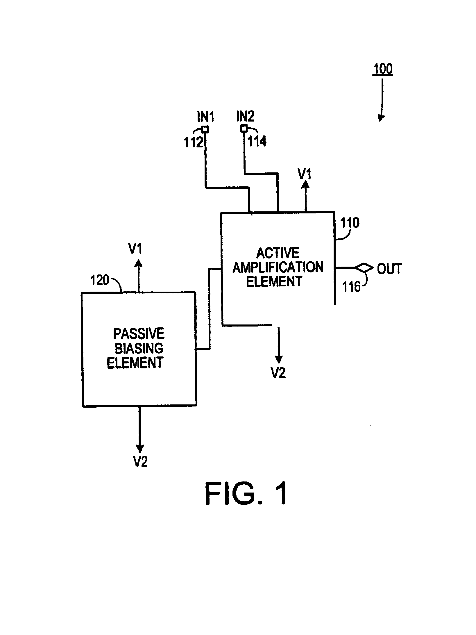
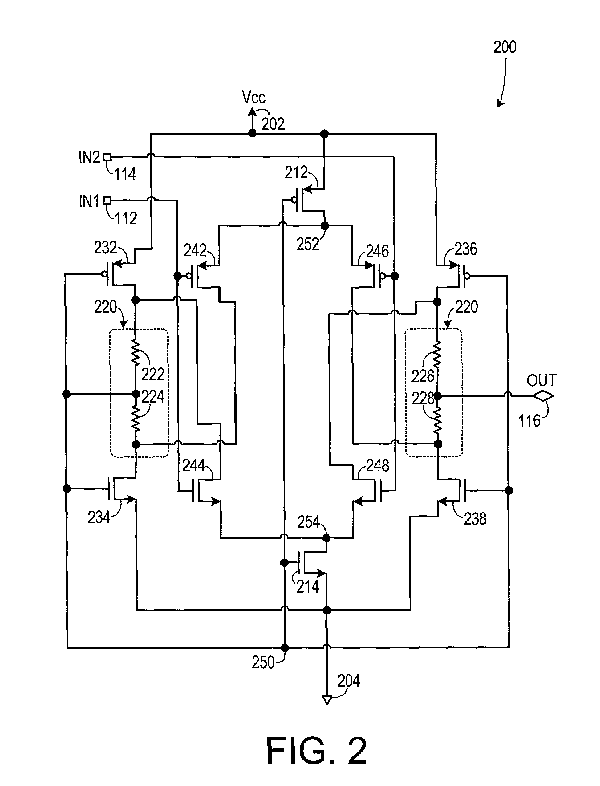
[0014]As shown in FIG. 1, one embodiment of the invention is a differential amplifier 100 for providing common-mode rejection while providing differential-mode amplification. The differential amplifier 100 includes an active differential amplification element 110 and a passive bias element 120. The active differential amplification element 110 is electrically coupled to a first input signal 112, a second input signal 114 and an output signal 116. It is also electrically coupled to a first voltage V1 and a different second voltage V2. Typically, the secon...


PUM


Abstract

A differential amplifier for providing common-mode rejection while providing differential-mode amplification includes an active differential amplification element electrically coupled to a first input signal, a second input signal and an output signal. The active differential amplification element is also electrically coupled to a first voltage and to a different second voltage. A passive bias element is electrically coupled to the active differential amplification element. The passive bias element is capable of biasing the active differential amplification element so that the active differential amplification element operates in a saturation mode. The active differential amplification element thereby generates the output signal so that the output signal corresponds to a voltage difference between the first input signal and the second input signal.

Description

BACKGROUND OF THE INVENTION[0001]1. Field of the Invention[0002]The present invention relates to electronic circuits and, more specifically, to a CMOS differential amplifier that reduces the speed-limiting effects of capacitance, as well as reducing the required level of the supply voltage.[0003]2. Description of the Prior Art[0004]Differential amplifiers sense two input signals and output a signal that is a function of the difference in values of the two input signals. One type of differential amplifier employs complementary metal-oxide semiconductor (CMOS) integrated circuits. CMOS differential amplifiers are used for various applications because a number of advantages can be derived from these types of amplifiers, as compared to single-ended amplifiers. Differential amplifiers are used to amplify analog, as well as digital signals, and can be used in various implementations to provide an output from the amplifier in response to differential inputs. They can be readily adapted to ...

Claims


Application Information

Patent Timeline
Patent Type & Authority Patents(United States)
IPC IPC(8): G06G7/26H03F3/45
CPCH03F3/4521
Inventor CECCHI, DELBERT RAYMONDHANSEN, CHARLES C.PREUSS, CURTIS WALTER
Owner TWITTER INC
Learn More