Apparatus and method for reduced loading of signal transmission elements

a signal transmission element and load reduction technology, applied in the field of circuits, devices and methods for transmitting signals along conductors, can solve the problems of difficult to achieve well-matched terminations, particularly in communications-receiving circuits designed to transmit or receive signals from transmission lines, and are particularly sensitive to signal return loss, so as to achieve less capacitance and less return loss of that signal.

Active Publication Date: 2011-10-18
MARVELL ASIA PTE LTD
View PDF18 Cites 1 Cited by
  • Summary
  • Abstract
  • Description
  • Claims
  • Application Information

AI Technical Summary

Benefits of technology

[0012]According to one aspect of the invention, an apparatus is provided which includes a common signal node operable to conduct a first signal, a first circuit coupled to the common signal node to utilize the first signal and a signal-handling element coupled to the common signal node. The signal-handling element includes an isolating circuit coupled to the first conductor, a second conductor operable to conduct an output of the isolating circuit, and a signal-handling circuit coupled to the second conductor. The signal-handling circuit is operable to perform a signal-handling function in response to the output of the isolating circuit. By virtue of the isolating circuit, the signal-handling circuit and the first circuit are isolated from the second conductor and the signal-handling circuit. Preferably, the achieved isolation permits a communication signal included in the first signal to be conducted within a communication apparatus with less capacitance, and producing less return loss of that signal.
[0013]According to another aspect of the invention, a communication apparatus is provided which includes a common signal node operable to conduct a first communication signal, a first circuit coupled to the common signal node to perform first analog signal processing of the first communication signal and a signal-handling element coupled to the common signal node. The signal-handling element includes an isolating circuit coupled to the first conductor, a second conductor operable to conduct an output of the isolating circuit, and a signal-handling circuit coupled to the second conductor. The signal-handling circuit is responsive to the output of the isolating circuit to perform a signal-handling function. By virtue of the isolating circuit, the signal-handling circuit and the first circuit are isolated from the second conductor and the signal-handling circuit. Advantageously, the achieved isolation may permit the communication signal to be conducted within the communication apparatus with less capacitance, and decrease an amount of return loss of that signal.

Problems solved by technology

Microelectronic circuits used in today's advanced systems, especially those designed to transmit or receive signals from transmission lines, are particularly sensitive to signal return loss.
Communications-receiving circuits are particularly sensitive to signal return loss at interfaces between transmission channels and front-end interfaces of receiving circuits.
However, achieving well-matched terminations can be problematic.
In some types of devices, particularly devices designed to receive signals from relatively long external transmission lines, such as high-speed SerDes circuits, loading of the critical wiring paths at the input interface can be a significant contributor to signal return loss.
However, such layout impacts the quality of the signal ultimately output at terminal 142 by the communications handling circuitry.
Such loading, in addition to junction and gate capacitance, inherently degrades the signal integrity in the HSS core.
However, Gupta et al. does not deal with capacitive loading at an input or output interface of communications transmission or receiving equipment.

Method used


Image

  • Apparatus and method for reduced loading of signal transmission elements
  • Apparatus and method for reduced loading of signal transmission elements
  • Apparatus and method for reduced loading of signal transmission elements

Examples


Embodiment Construction

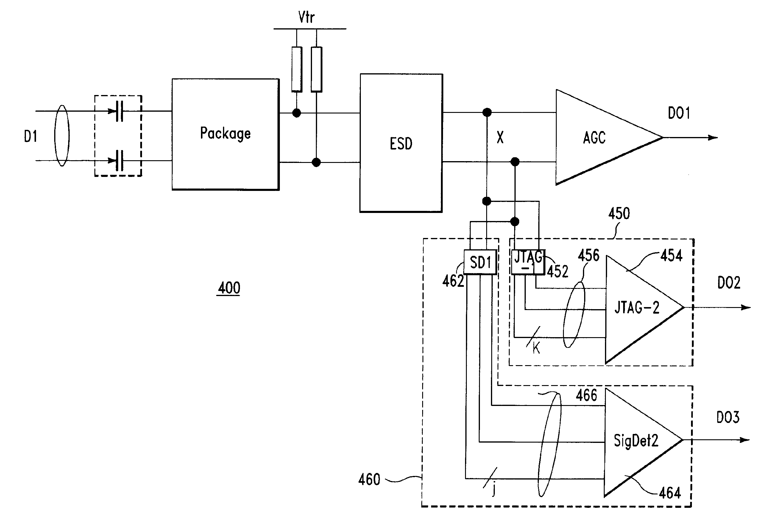
[0028]According to an embodiment of the invention described herein, an apparatus is provided in which a first signal, for example, an information-bearing signal such as a data signal, a control signal, or a clock signal, is conducted on a first conductor via a common node to a first circuit. The first circuit receives, conditions or otherwise utilizes the first signal. Illustratively, the first conductor defines a critical signal path. One or more signal-handling elements are also connected to the common node, such signal-handling element also receiving, conditioning, or otherwise utilizing the first signal. In one example, the signal handling element is an element which determines a state of the first signal in response to detecting a condition present at the common signal node. The signal-handling element includes an isolating circuit coupled to the common node, which is operable to output a second signal on a second conductor. The isolating circuit is operable to isolate the firs...


PUM

PropertyMeasurementUnit
frequenciesaaaaaaaaaa
impedanceaaaaaaaaaa
parasitic capacitanceaaaaaaaaaa

Abstract

An apparatus is provided which includes a common signal node operable to conduct a first signal, a first circuit coupled to the common signal node to utilize the first signal and a signal-handling element coupled to the common signal node. The signal-handling element includes an isolating circuit coupled to the first conductor, a second conductor operable to conduct an output of the isolating circuit, and a signal-handling circuit coupled to the second conductor. The signal-handling circuit is operable to perform a signal-handling function in response to the output of the isolating circuit. By virtue of the isolating circuit, the signal-handling circuit and the first circuit are isolated from the second conductor and the signal-handling circuit. Preferably, the achieved isolation permits a communication signal included in the first signal to be conducted within a communication apparatus with less capacitance, and producing less return loss of that signal.

Description

BACKGROUND OF THE INVENTION[0001]The present invention relates to circuits, devices and methods for transmitting signals along conductors, especially transmission lines.[0002]Transmission lines are frequently provided by pairs of conductors used to carry signals between one integrated circuit (“IC”) or “chip” and another chip, e.g., as provided on a circuit board or wiring substrate. A transmission line has a signal conductor, e.g., a wire, or conductive trace, which is typically maintained at a constant or nearly constant spacing with respect to a ground conductor or other reference conductor. For example, a transmission line can include a first signal-carrying wire held at a constant spacing relative to a ground plane in the case of a microstrip line. In another example, a conductive sheathing forms the reference conductor, such as in the case of a coaxial cable.[0003]In a particular example, transmission lines are provided as a combination of wiring and ground conductors used to ...

Claims


Application Information

Patent Timeline
Patent Type & Authority Patents(United States)
IPC IPC(8): G01R31/08H04L1/00H04L12/26H04J3/14G06F11/00H03K17/16H04J1/16G08C15/00G01N30/86H03K19/0175H03K9/00H03K5/01G05F1/00H03K5/00
CPCG06F13/4072
Inventor HSU, LOUIS L.SELANDER, KARL D.SORNA, MICHAEL A.STORASKA, DANIEL W.
Owner MARVELL ASIA PTE LTD
Why Eureka
Try Eureka