Color filter substrate and liquid crystal display device
a color filter substrate and liquid crystal display technology, applied in the direction of optics, instruments, optical elements, etc., can solve the problems of difficult color design of such a liquid crystal display panel, difficulty in alignment control by rubbing alignment films, and disclination of surrounding normal dots, so as to suppress the occurrence of both a switching domain and disclination, and suppress the effect of a decrease in the aperture ratio
- Summary
- Abstract
- Description
- Claims
- Application Information
AI Technical Summary
Benefits of technology
Problems solved by technology
Method used
Image
Examples
embodiment 1
[0039]The liquid crystal display device of the present embodiment is a TN liquid crystal display device provided with a TFT substrate and a color filter substrate which face each other. The liquid crystal display device has spacers to maintain a certain space between the substrates. The TFT substrate and the color filter substrate are attached via a sealing agent. A liquid crystal material containing liquid crystal molecules (nematic liquid crystals) having positive dielectric anisotropy is filled between the substrates such that a liquid crystal layer is formed. The liquid crystal layer is in a horizontal alignment mode in which liquid crystal molecules are aligned substantially in parallel with the substrates when no voltage is applied between the substrates. Here, the TFT substrate has a common structure. For example, the TFT substrate has, on a transparent substrate, wirings such as source lines, gate lines, and Cs lines (storage capacitor wirings); TFTs which are switching elem...
example 1
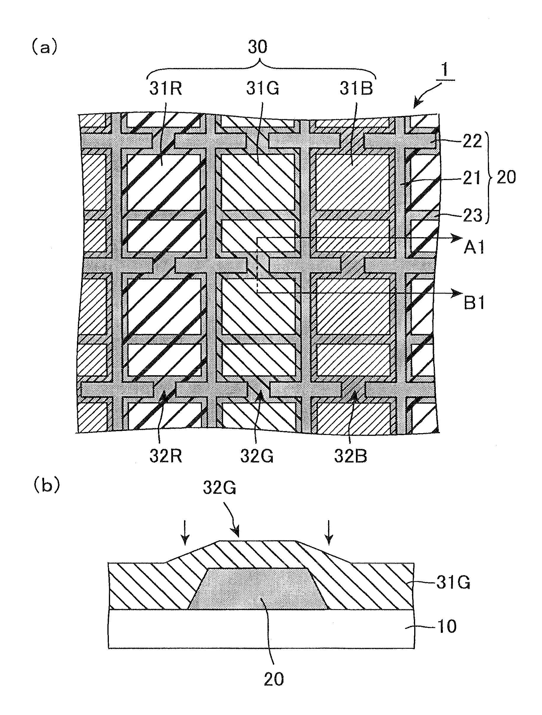
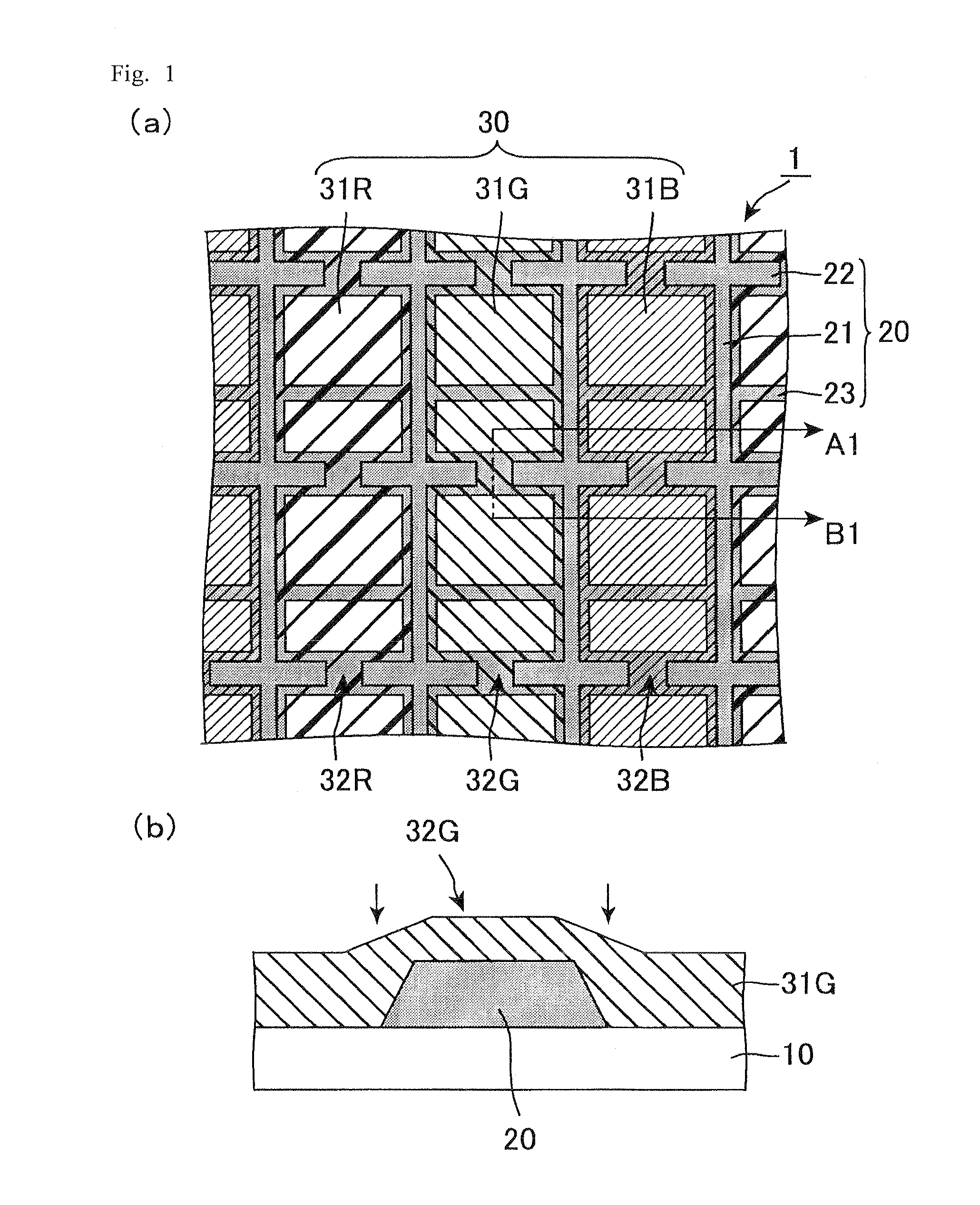
[0092]As illustrated in FIG. 7, a color filter substrate that is the same as the color filter substrate 1 illustrated in FIG. 1 was produced. Specifically, a black photosensitive resin composition was applied on a glass substrate and was patterned into the black matrix 20 having a thickness of 1.1 μm. On the black matrix 20, liquid color resists were applied and patterned into the respective color filters 31R, color filters 31G, and color filters 31B, in the stated order. The color filter 31R, the color filter 31G, and the color filter 31B each had a thickness of 1.9 μm in the dot openings, and had a thickness of from 1.0 to 1.4 μm on the black matrix 20. As a result, the color filter 31R, the color filter 31G, and the color filter 31B had elevation changes, resulting from the black matrix 20, of from 0.2 to 0.6 micrometers.
[0093]The dot pitch in the vertical direction (vertical pitch) in FIG. 7 was 159 μm. The dot pitch in the horizontal direction (horizontal pitch) in FIG. 7 was 5...
example 2
[0095]Liquid crystal display devices for the verification test were produced which had the same configuration as that of the liquid crystal display device of Example 1, except that the ratio We / Wb was changed to 0.38.
PUM
| Property | Measurement | Unit |
|---|---|---|
| width | aaaaa | aaaaa |
| width | aaaaa | aaaaa |
| thickness | aaaaa | aaaaa |
Abstract
Description
Claims
Application Information
 - R&D
- Intellectual Property
- Life Sciences
- Materials
- Tech Scout
- Unparalleled Data Quality
- Higher Quality Content
- 60% Fewer Hallucinations
Browse by: Latest US Patents, China's latest patents, Technical Efficacy Thesaurus, Application Domain, Technology Topic, Popular Technical Reports.
© 2025 PatSnap. All rights reserved.Legal|Privacy policy|Modern Slavery Act Transparency Statement|Sitemap|About US| Contact US: help@patsnap.com


