Clothes dryer

a dryer and cloth technology, applied in the field of cloth dryers, can solve the problems of difficult to fabricate the first duct, difficult to use gas as heat source, and carbon monoxide generated after combustion, and achieve the effect of effectively sealing a part and being easy to recogniz

Inactive Publication Date: 2013-06-25
LG ELECTRONICS INC
View PDF27 Cites 25 Cited by
  • Summary
  • Abstract
  • Description
  • Claims
  • Application Information

AI Technical Summary

Benefits of technology

[0017]Therefore, it is an object of the present invention to provide a clothes dryer capable of preventing lint from leaking through a gap of a filter installation space, and capable of providing means to inform whether a filter has been mounted to a precise position or not.
[0021]The filter assembly may further comprise a cover guide 530 coupled to the cover filter 520 in a state that the lint filter 510 is disposed between the cover filter 520 and the cover guide 530. This may enhance a sealing state for lint collection.
[0023]In the present invention, the lint filter inserted into the clothes dryer may be configured to contact the cover guide, thereby effectively sealing a part where the filter assembly is to be installed. This may prevent lint from leaking through a gap of the filter assembly position, and may allow a user to easily recognize whether the lint filter has been mounted to a precise position or not before the clothes dryer operates.

Problems solved by technology

Furthermore, since products generated after combustion, such as carbon monoxide, is also exhausted out, the exhaustion duct has to be installed with a length long enough to be extended to the outdoor.
However, since flow of the dried air forms a closed loop, using gas as a heat source is not easy.
Due to the materials different each other, it is not easy to fabricate the first duct 210 and the lint filter 310 in the same shape.
This may degrade the function of the clothes dryer.
However, the conventional clothes dryer is not provided with means to inform a user whether the filter has been mounted to a precise position or not.

Method used


Image

  • Clothes dryer
  • Clothes dryer
  • Clothes dryer

Examples


Embodiment Construction

[0036]Reference will now be made in detail to the preferred embodiments of the present invention, examples of which are illustrated in the accompanying drawings.

[0037]Hereinafter, a filtering structure for a clothes dryer, and a clothes dryer having the same according to the present invention will be explained in more detail with reference to the attached drawings.

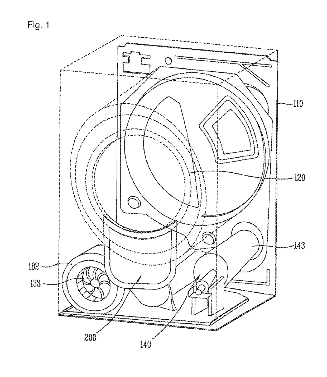
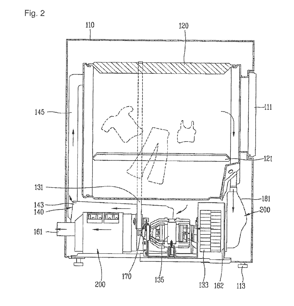
[0038]The clothes dryer according to the present invention comprises a filter assembly for filtering lint included in air exhausted from a drum rotatably installed in a body.

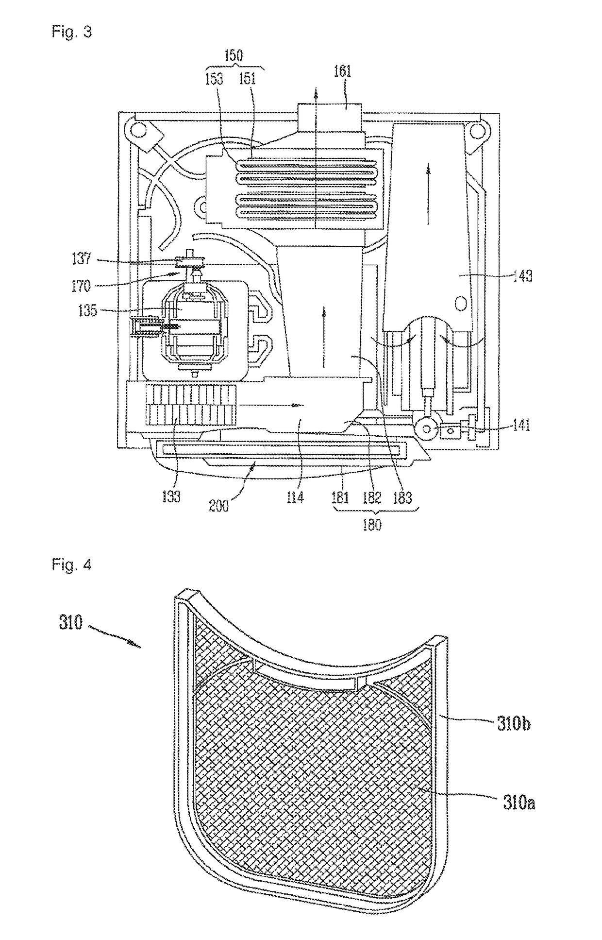
[0039]FIGS. 8 to 10 are perspective views showing a lint filter 510, a cover filter 520, and a cover guide 530 that constitute the filter assembly according to the present invention. FIG. 8 is an exploded perspective view showing the respective components.

[0040]The filter assembly of the present invention includes the lint filter 510, the cover filter 520, and the cover guide 530.

[0041]The lint filter 510 consists of a mesh portion 510a, and a mesh fra...


PUM


Abstract

Disclosed is a clothes dryer, comprising: a body; a drum rotatably installed at the body; a duct for guiding air exhausted from the drum; and a filter assembly for filtering lint included in the air exhausted from the drum. The filter assembly includes a lint filter and a cover filter, and a lint collector encompassed by the lint filter and the cover filter. The clothes dryer includes sensing means for sensing whether the lint filter has been mounted to a precise position or not. The sensing means consists of a magnet mounted to a mesh frame of the lint filter, and a reed switch mounted to a cover guide.

Description

TECHNICAL FIELD[0001]The present invention relates to a clothes dryer having a filter for filtering lint, and more particularly, to a clothes dryer having a filter assembly capable of preventing lint from leaking through a gap of a filter installation space.BACKGROUND ART[0002]Generally, a clothes dryer serves to dry an object to be dried by absorbing moisture inside the object by blowing blast generated by an electric heater or a gas heater into a drum. According to a method for processing humid air generated when drying the object, the clothes dryer is largely classified into an exhaustion-type clothes dryer and a condensation-type clothes dryer.[0003]According to the exhaustion-type clothes dryer, humid air exhausted from the drum is exhausted out of the clothes dryer. However, required is an exhaustion duct for exhausting moisture evaporated from inside of the drum to outside. Furthermore, since products generated after combustion, such as carbon monoxide, is also exhausted out,...

Claims


Application Information

Patent Timeline
Patent Type & Authority Patents(United States)
IPC IPC(8): F26B11/02
CPCD06F58/22D06F58/04D06F58/20
Inventor KIM, JAE-SEOKYOON, JU-HAN
Owner LG ELECTRONICS INC
Why Eureka
Try Eureka