Electric propulsion apparatus

a technology of electric propulsion and thrusters, which is applied in the direction of machines/engines, cosmonautic vehicles, transportation and packaging, etc., can solve the problem of not having a single electric propulsion thruster (ept)

Active Publication Date: 2013-06-25
NASA
View PDF11 Cites 17 Cited by
  • Summary
  • Abstract
  • Description
  • Claims
  • Application Information

AI Technical Summary

Benefits of technology

[0013]The magnetic field thus ensures that the discharge power predominately goes into accelerating the xenon propellant and not the electrons, and the thruster turns out to be reasonably efficient.

Problems solved by technology

One limitation is that no single Electric Propulsion Thruster (EPT) exists which can operate over the full specific impulse range of interest and do so with the combined characteristics of both Hall-effect and ion thrusters, such as high Thrust-to-Power (T / P).

Method used


Image

  • Electric propulsion apparatus
  • Electric propulsion apparatus
  • Electric propulsion apparatus

Examples


Embodiment Construction

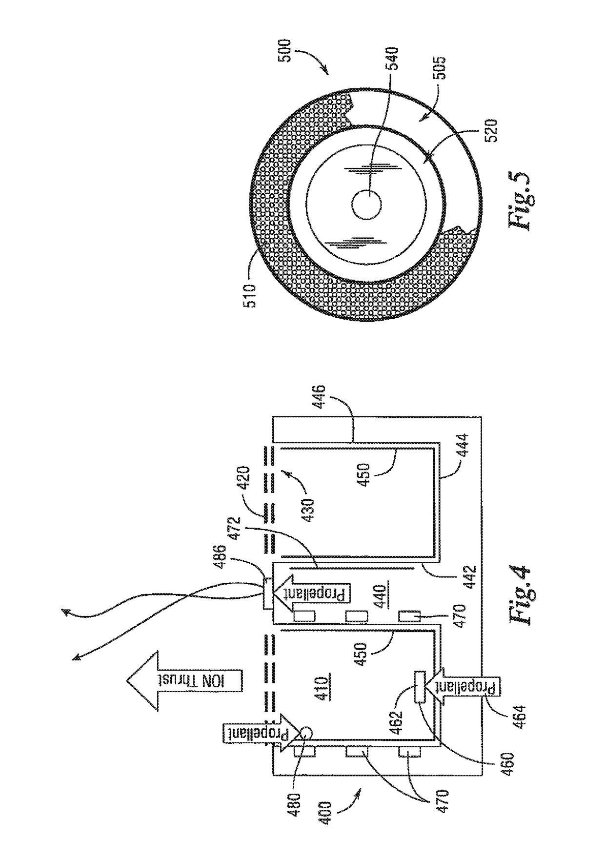
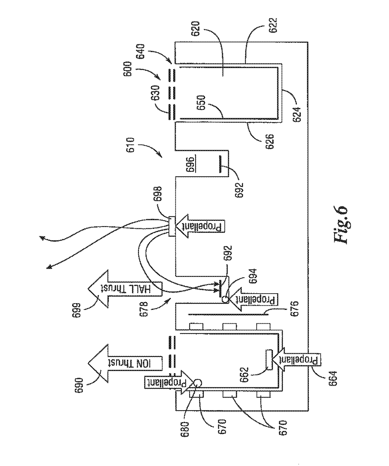
[0035]As used herein, the relevant design attributes of a Hall-effect and ion thrusters are their respective ion-acceleration systems: an azimuthally-symmetric channel with axial E-field and radial B-field for the Hall-effect thruster yielding closed-drift electrons to generate a plasma and create counter-flowing accelerated ion current; and closely-spaced multi-aperture electrodes or electrostatic ion optics with a large applied E-field to focus and accelerate ions from a discharge plasma to form a space-charge-limited mono-energetic beam for the ion thruster.

[0036]The plasma production and acceleration mechanisms of the Hall thruster are closely-coupled and are intimately connected to the geometric construction of the thruster discharge geometry.

[0037]On the other hand ion thrusters have de-coupled plasma production and acceleration mechanisms. As such, the thruster discharge geometry can be constructed in a variety of fashions without compromising the operational integrity of the...


PUM


Abstract

An electric propulsion machine includes an ion thruster having an annular discharge chamber housing an anode having a large surface area. The ion thruster includes flat annular ion optics with a small span to gap ratio. Optionally, a second electric propulsion thruster may be disposed in a cylindrical space disposed within an interior of the annulus.

Description

CROSS-REFERENCE TO RELATED APPLICATIONS[0001]This application claims priority to U.S. Provisional Application Ser. No. 61 / 295,326 filed Jan. 15, 2010.ORIGIN OF THE INVENTION[0002]The invention described herein was made by employees of the United States Government and may be manufactured and used by or for the Government for Government purposes without the payment of any royalties thereon or therefore.BACKGROUND[0003]Two general types of electric propulsion thrusters used in space include ion thrusters and Hall-effect thrusters.[0004]Both ion thrusters and Hall-effect thrusters are ‘electrostatic’ electric propulsion devices used for spacecraft propulsion that create thrust by accelerating ions. The thrust created is very small compared to conventional chemical rockets, but a very high specific impulse, or high exhaust velocity, which reduces the propellant requirements for missions is obtained. This high ‘propellant efficiency’ is achieved through the very frugal propellant consumpt...

Claims


Application Information

Patent Timeline
Patent Type & Authority Patents(United States)
IPC IPC(8): F03H1/00
CPCF03H1/0043F03H1/0075B64G1/405F03H1/0037H01J27/024
Inventor PATTERSON, MICHAEL J.
Owner NASA
Why Eureka
Try Eureka