
Autonomous grain combine control system

Inactive Publication Date: 2013-06-25
THE UNITED STATES AS REPRESENTED BY THE DEPARTMENT OF ENERGY
View PDF8 Cites 33 Cited by
  • Summary
  • Abstract
  • Description
  • Claims
  • Application Information

AI Technical Summary

Benefits of technology

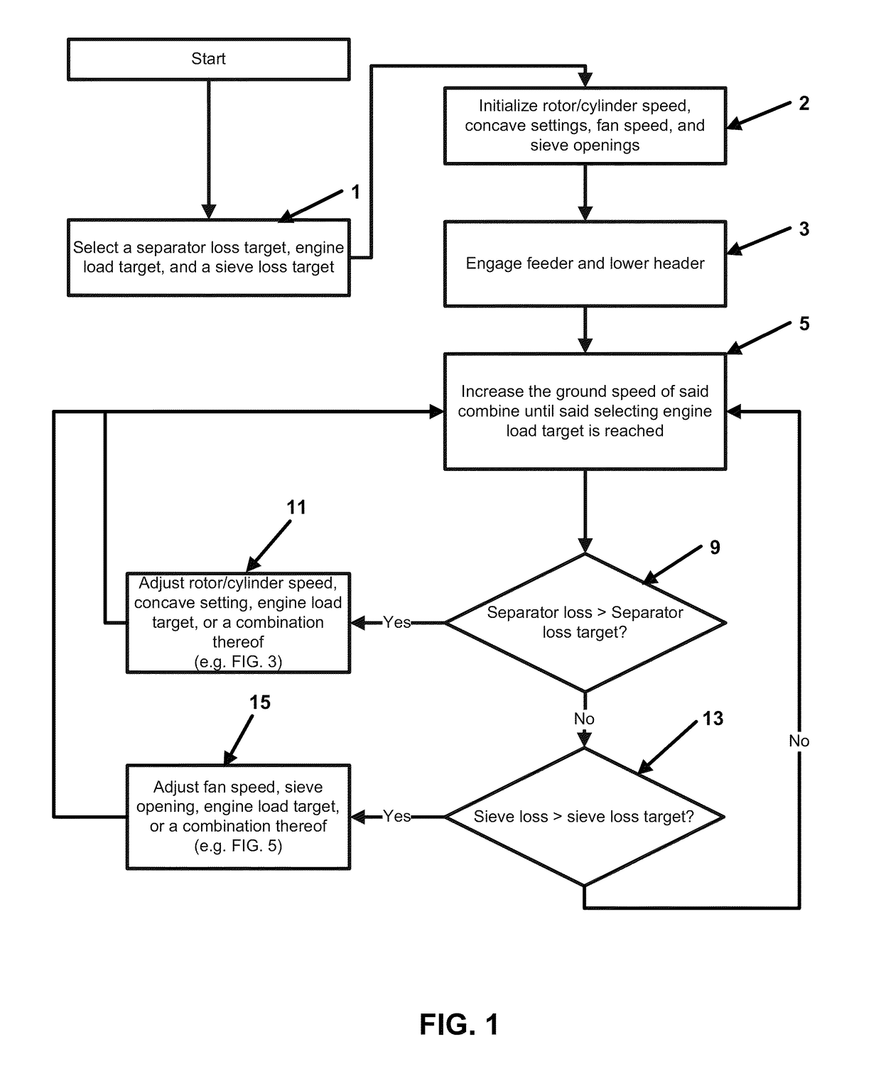
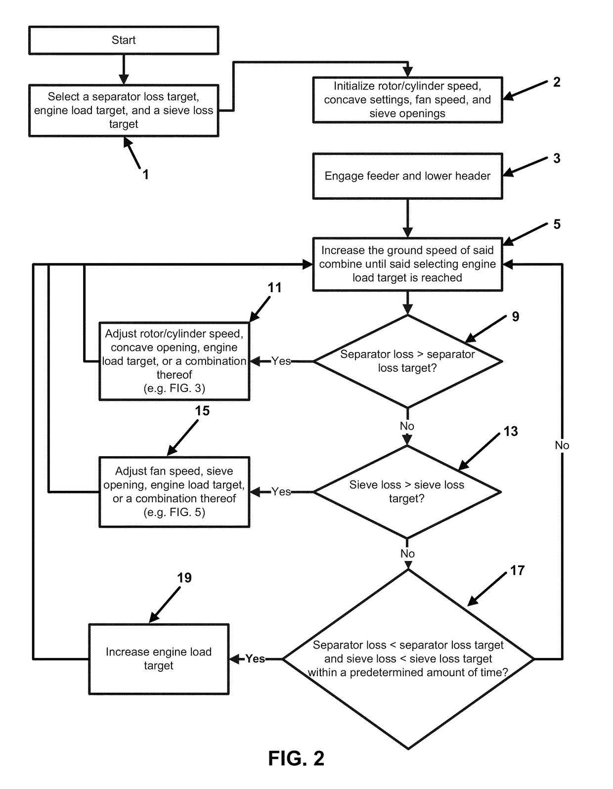
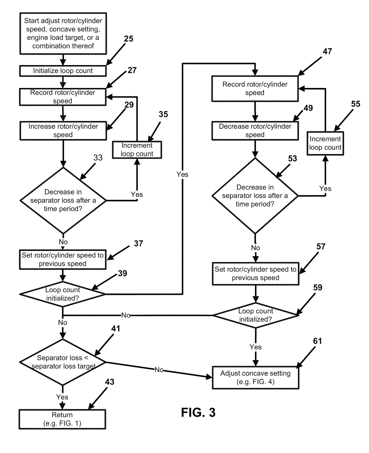
The patent describes a system for controlling the loss of grain during the harvesting process. The system uses a grain combine with a feeder and a header to collect the grain. A target is set for the amount of grain to be lost during the process, and the speed of the grain combine, engine load, and the settings of the separating and sifting mechanisms are adjusted to achieve that target. If the target is not reached, the engine load and speed of the grain combine are reduced to decrease the loss of grain. This system helps to improve the performance of the grain combine and reduce the amount of grain lost during the harving process.

Problems solved by technology

There are many factors that influence production cost, such as agricultural output, employee cost, and energy costs.
However, employee cost, arising from employee time, and energy costs have been difficult to balance.
However, given the decline of traditional family owned and operated farms and the rise of outsourced harvesting, there has been a large decrease in the level of experience of the operators harvesting crops.
This leaves the operator with little incentive to maximize harvesting output or to minimize crop loss or energy consumption.
Sadly, this leads to suboptimal harvesting and therefore wasted crops, wasted energy, or both.
However, an unskilled operator or even a skilled operator operating a grain combine in an unfamiliar field or unfamiliar conditions, such as plant density or moisture, is ill-equipped to properly adjust these grain combine operating conditions.
In many cases, due to the complexity and interaction of such adjustments, only the ground speed is altered if the operator determines that excess crop is being lost.
Additionally, even if the operator could account for all of the changes during harvesting, constantly changing all of these adjustments would overly distract the operator from his primary concerns for proper grain combine operation and safety.

Method used


Image

  • Autonomous grain combine control system
  • Autonomous grain combine control system
  • Autonomous grain combine control system

Examples


Embodiment Construction

[0021]A system for controlling a grain combine comprising a control system. The grain combine comprising a rotor / cylinder, a sieve, a fan, a concave, a feeder, a header, and an engine. The system has two main functions, a grain loss control and biomass feed rate control. The purpose of the grain loss control is to control grain loss to a preselected limit by adjusting components of the combine separator and cleaning systems. The feed rate control is to control combine ground speed in order to maintain optimum performance of the combine as crop conditions and field conditions vary.

[0022]The grain loss (an aggregate of separator loss and sieve loss) control is described as follows: The feeder of the combine is engaged and the header is lowered. A separator loss target, engine load target, and a sieve loss target are selected. Grain is harvested with the lowered header passing the grain through the engaged feeder. Separator loss, sieve loss, engine load and ground speed of the combine ...


PUM


Abstract

A system for controlling a grain combine having a rotor / cylinder, a sieve, a fan, a concave, a feeder, a header, an engine, and a control system. The feeder of the grain combine is engaged and the header is lowered. A separator loss target, engine load target, and a sieve loss target are selected. Grain is harvested with the lowered header passing the grain through the engaged feeder. Separator loss, sieve loss, engine load and ground speed of the grain combine are continuously monitored during the harvesting. If the monitored separator loss exceeds the selected separator loss target, the speed of the rotor / cylinder, the concave setting, the engine load target, or a combination thereof is adjusted. If the monitored sieve loss exceeds the selected sieve loss target, the speed of the fan, the size of the sieve openings, or the engine load target is adjusted.

Description

GOVERNMENT INTERESTS[0001]The United States Government has rights in this invention pursuant to Contract No. DE-AC07-991D13727, between the U.S. Department of Energy (DOE) and Bechtel BWXT Idaho LLC.FIELD OF THE INVENTION[0002]The present invention relates to a system and method for optimally controlling a grain combine.BACKGROUND OF THE INVENTION[0003]The goal of agricultural production is to maximize profit. A major way to do this is to minimize production cost. There are many factors that influence production cost, such as agricultural output, employee cost, and energy costs. Throughout the years, agricultural output has been maximized using factors such as the amount of water received by the growing crop, the amount and type of fertilizer provided to the crop, the amount and type of herbicides and pesticides applied to the crop, etc. However, employee cost, arising from employee time, and energy costs have been difficult to balance.[0004]Traditionally, harvesting was performed b...

Claims


Application Information

Patent Timeline
IPC IPC(8): A01D75/18
CPCA01D41/127
Inventor HOSKINSON, REED L.KENNEY, KEVIN L.LUCAS, JAMES R.PRICKEL, MARVIN A.
Owner THE UNITED STATES AS REPRESENTED BY THE DEPARTMENT OF ENERGY
Learn More