
Neck sparing total hip implant system

a total hip and implant technology, applied in the field of orthopedic implants, can solve the problems of hardly being called tissue sparing, requiring relatively large exposure, and a multitude of limitations of surface replacement devices

Inactive Publication Date: 2013-06-25
CONCEPT DESIGN & DEV
View PDF42 Cites 9 Cited by
  • Summary
  • Abstract
  • Description
  • Claims
  • Application Information

AI Technical Summary

Problems solved by technology

Surface replacement devices have a multitude of limitations.
First, the procedure can require relatively large exposure and therefore can hardly be called tissue sparing, although bone sparing.
Second, the compromised bone of the femoral head is often a poor foundation and can cause early or late failure from collapse.
Lastly, femoral neck fracture can occur.
Some have considered the proximal femoral metaphyseal bone incapable of sustaining load.
Modern minimally invasive surgery, in particular, the “anterior supine muscle sparing” approach, is made more difficult by the straight diaphyseal engaging stems.
However, femoral insertion can still be very challenging.

Method used


Image

  • Neck sparing total hip implant system
  • Neck sparing total hip implant system
  • Neck sparing total hip implant system

Examples


Embodiment Construction

[0038]For the purposes of promoting an understanding of the principles in accordance with the disclosure, reference will now be made to the embodiments illustrated in the drawings and specific language will be used to describe the same. It will nevertheless be understood that no limitation of the scope of the disclosure is thereby intended. Any alterations and further modifications of the inventive features illustrated herein, and any additional applications of the principles of the disclosure as illustrated herein, which would normally occur to one skilled in the relevant art and having possession of this disclosure, are to be considered within the scope of the disclosure claimed.

[0039]It is to be understood that this disclosure is not limited to the particular configurations, process steps, and materials disclosed herein as such configurations, process steps, and materials may vary somewhat. It is also to be understood that the terminology employed herein is used for the purpose o...


PUM


Abstract

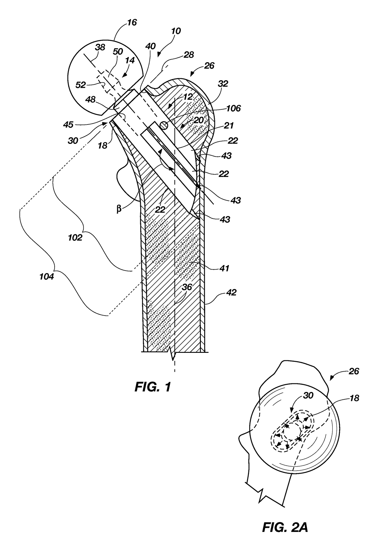
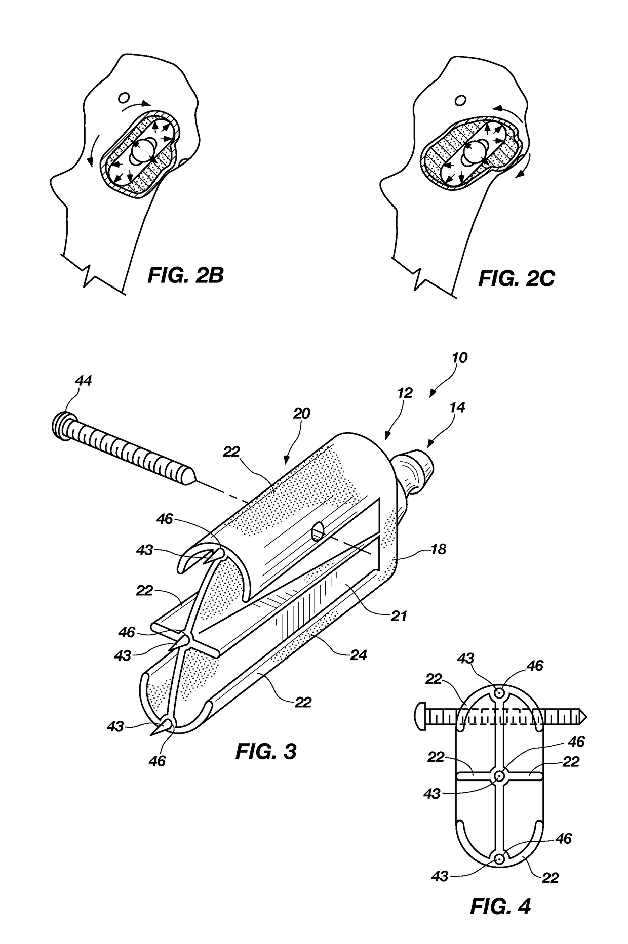
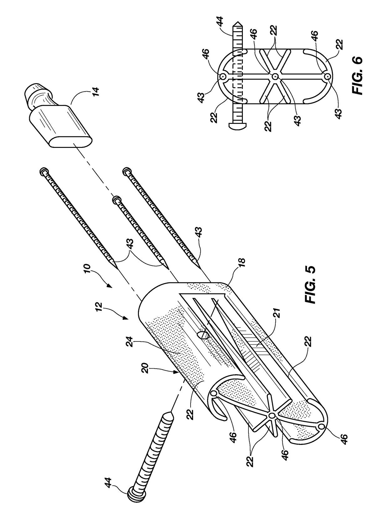
A femoral prosthesis. The femoral prosthesis includes an implant body having a proximal end and a distal end and a shoulder at the proximal end, the shoulder being structured and dimensioned for a tight press fit into the neck of a femur. The implant body includes a trunk at the distal end, the trunk having a wedge formed by a tapered portion extending in the direction of the distal end of the implant body. The implant body also includes a medial column extending from the shoulder toward the distal end and a lateral column extending from the shoulder toward the distal end. The wedge, the medial column, and the lateral column to provide multi-planar stability for the implant body and surface area for fixation of the implant body.

Description

CROSS-REFERENCE TO RELATED APPLICATIONS[0001]This application is a continuation-in-part of U.S. application Ser. No. 12 / 874,132, filed Sep. 1, 2010, which claims the benefit of U.S. Provisional Application No. 61 / 238,898, filed Sep. 1, 2009, entitled FEMORAL PROSTHESIS, which are both hereby incorporated by this reference herein in their entireties, including but not limited to those portions that specifically appear hereinafter, the incorporation by reference being made with the following exception: In the event that any portion of the above-referenced provisional applications is inconsistent with this application, this application supercedes said portion of said above-referenced provisional applications.STATEMENT REGARDING FEDERALLY SPONSORED RESEARCH OR DEVELOPMENT[0002]Not Applicable.BACKGROUND[0003]1. The Field of the Present Disclosure[0004]The present disclosure relates generally to an orthopedic implant for use in a total hip arthroplasty, i.e., a total hip replacement. More...

Claims


Application Information

Patent Timeline
Patent Type & Authority Patents(United States)
IPC IPC(8): A61F2/36
CPCA61F2/3601A61F2/3662A61F2/3609A61B17/1668A61B17/175A61F2002/30205A61F2002/30321A61F2002/30334A61F2002/30841A61F2002/30904A61F2002/365A61F2002/3652A61F2002/3668A61F2002/368A61F2002/30884
Inventor WALTER, BRADLEYBRAZIL, DECLANMCTIGHE, TIMOTHY
Owner CONCEPT DESIGN & DEV
Learn More