Microwave-assisted magnetic recording head having a current confinement structure

a technology of microwaves and magnetic recording heads, applied in the field of magnetic recording heads, can solve the problems of preventing the achievement of the desired write performance and recording track width, and the alignment of a sto b>10/b> at the center of a main pole b>9/b> in an acceptablely high yield process

Active Publication Date: 2013-06-25
WESTERN DIGITAL TECH INC
View PDF14 Cites 60 Cited by
  • Summary
  • Abstract
  • Description
  • Claims
  • Application Information

AI Technical Summary

Benefits of technology

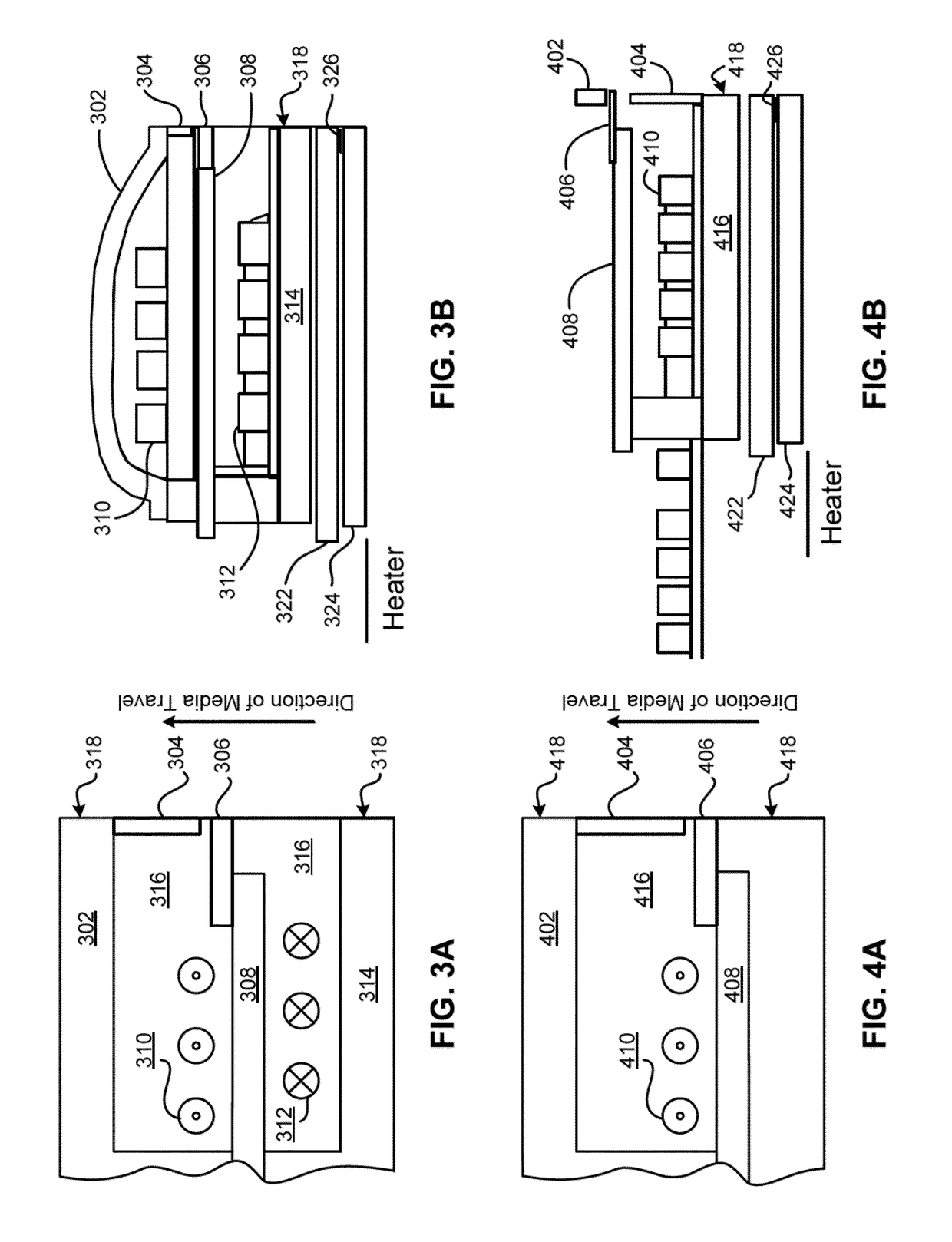
[0007]In one embodiment, a MAMR head includes a main pole adapted for producing a writing magnetic field, a STO positioned above the main pole, a low-resistance layer positioned above the STO, and a current confinement layer positioned between the low-resistance layer and the main pole, wherein the main pole and the low-resistance layer are adapted for acting as poles for writing data to a magnetic medium in response to a flow of current to the STO positioned therebetween to generate a high-frequency magnetic field which overlaps with the writing magnetic field, and wherein the current confinement layer is adapted for controlling a current density and / or a current density distribution of the current flowing to the STO.

Problems solved by technology

In existing pattern alignment technology, as shown in FIG. 6B according to the prior art, the alignment of a STO 10 at a center of a main pole 9 that is created in an acceptably-high yield process has proved problematic using conventional systems and methods.
When misalignment occurs, it affects both the switching field reduction effect on the recording medium and the write width on the recording medium which, in turn, precludes achieving the desired write performance and recording track width.

Method used


Image

  • Microwave-assisted magnetic recording head having a current confinement structure
  • Microwave-assisted magnetic recording head having a current confinement structure
  • Microwave-assisted magnetic recording head having a current confinement structure

Examples


Embodiment Construction

[0033]The following description is made for the purpose of illustrating the general principles of the present invention and is not meant to limit the inventive concepts claimed herein. Further, particular features described herein can be used in combination with other described features in each of the various possible combinations and permutations.

[0034]Unless otherwise specifically defined herein, all terms are to be given their broadest possible interpretation including meanings implied from the specification as well as meanings understood by those skilled in the art and / or as defined in dictionaries, treatises, etc.

[0035]It must also be noted that, as used in the specification and the appended claims, the singular forms “a,”“an,” and “the” include plural referents unless otherwise specified.

[0036]The following descriptions provide examples and embodiments of high-frequency magnetic field assisted recording heads, which may be used for recording data to magnetic media. The high-fr...


PUM

PropertyMeasurementUnit
frequencyaaaaaaaaaa
frequencyaaaaaaaaaa
current densityaaaaaaaaaa

Abstract

According to one embodiment, a high-frequency magnetic field-assisted magnetic recording head includes a main pole adapted for producing a writing magnetic field, a STO positioned above the main pole, a low-resistance layer positioned above the STO, and a current confinement layer positioned between the low-resistance layer and the main pole, wherein the main pole and the low-resistance layer are adapted for acting as poles for writing data to a magnetic medium in response to a flow of current to the STO positioned therebetween to generate a high-frequency magnetic field which overlaps with the writing magnetic field, and wherein the current confinement layer is adapted for controlling a current density and/or a current density distribution of the current flowing to the STO. Other magnetic recording heads and methods of production thereof are also described according to more embodiments.

Description

FIELD OF THE INVENTION[0001]The present invention relates to magnetic recording heads, and more particularly, to a microwave-assisted magnetic recording head having a current confinement structure.BACKGROUND[0002]One method to achieve higher recording density using a magnetic head mounted in a hard disk device is to narrow the pitch and / or the bits of the track that are written to the magnetic recording medium (e.g., the hard disk). Referring to FIG. 5A which shows a conventional magnetic write head having a main pole 9, a side gap 8, side shields 7, a trailing gap 18, a trailing shield 14, and a high Bs (saturation magnetic flux density) trailing shield area 19, as a result of narrowing either of the pitch and / or the bits of the track, the area of the main pole 9 on the air-bearing surface (ABS) decreases remarkably, with an accompanying increase in the recording density. The magnetic field generated from the main pole 9 is also reduced in accordance with the narrowing width of the...

Claims


Application Information

Patent Timeline
Patent Type & Authority Patents(United States)
IPC IPC(8): G11B5/127
CPCG11B5/1278G11B5/3133G11B5/3146G11B5/3163G11B2005/0024
Inventor KUSUKAWA, KIKUOSHIIMOTO, MASATOHOSOMI, KAZUHIKOWATANABE, KATSURO
Owner WESTERN DIGITAL TECH INC
Why Eureka
Try Eureka