Supercharge Your Innovation With Domain-Expert AI Agents!

Valve timing control device

a timing control and valve technology, applied in valve details, valve arrangements, machines/engines, etc., can solve the problems of reducing energy efficiency, affecting the accuracy of phase control of valve opening/closing timing, and ineffective use of oil pressure from an oil pump for controlling valve timing

Inactive Publication Date: 2013-07-02
DENSO CORP
View PDF6 Cites 0 Cited by
  • Summary
  • Abstract
  • Description
  • Claims
  • Application Information

AI Technical Summary

Benefits of technology

This patent is about a device that controls the timing of when a valve in an engine opens and closes. It includes a housing, a rotor, and a sealing plate. The rotor is inside the housing and can rotate to change the timing of the valve. The device also has chambers that hold oil to control the timing. The sealing plate is in contact with the rotor and helps to regulate its timing. A regulating portion is inside the rotor and works with a recess in the sealing plate to control the timing. The device helps to improve engine performance by controlling the timing of valves.

Problems solved by technology

When the internal leakage occurs, oil pressure from an oil pump cannot be effectively used for controlling the valve timing.
As a result, energy efficiency may be decreased and accuracy for phase control by valve opening / closing timing may be decreased.

Method used


Image

  • Valve timing control device
  • Valve timing control device
  • Valve timing control device

Examples


first embodiment

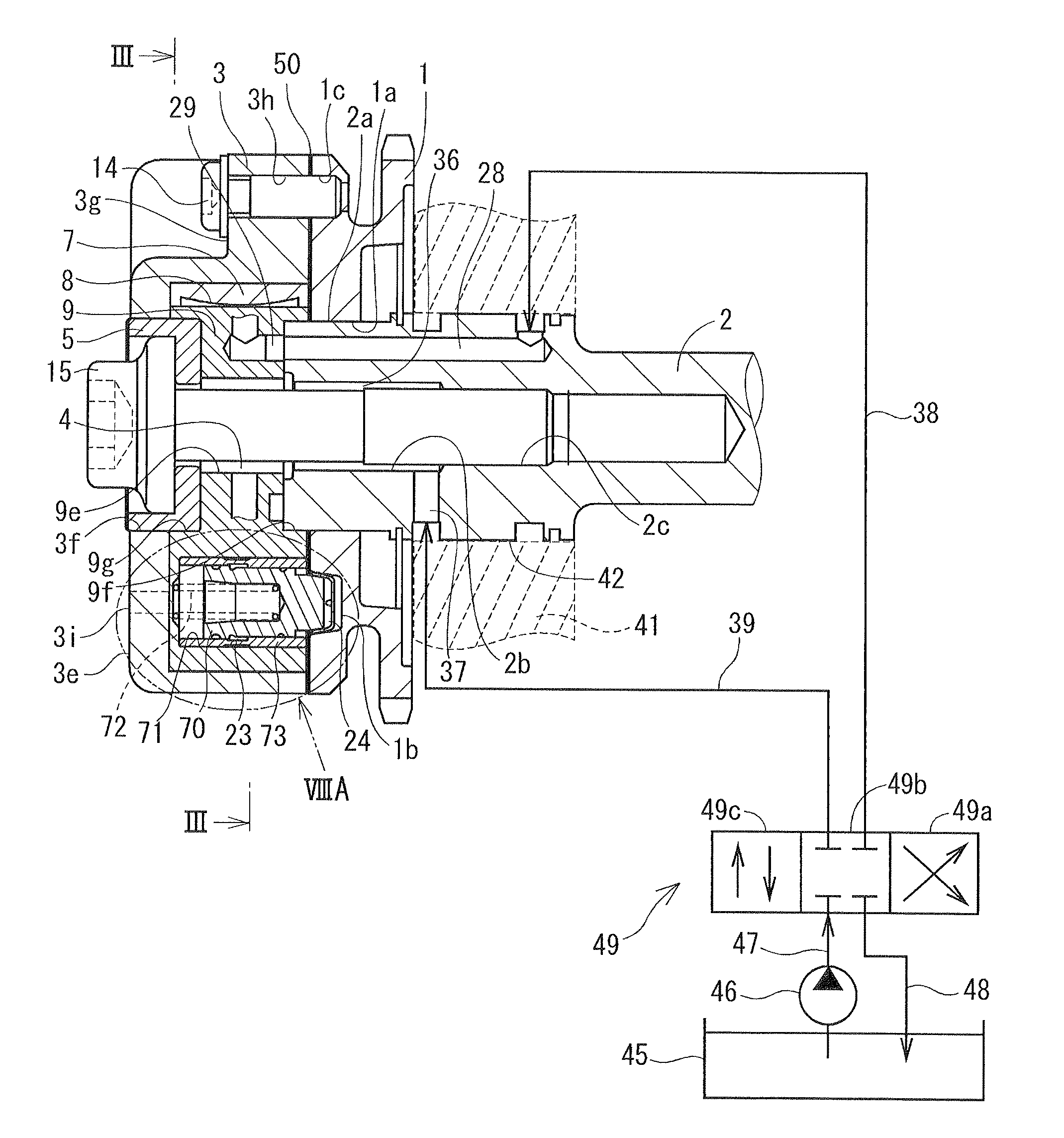
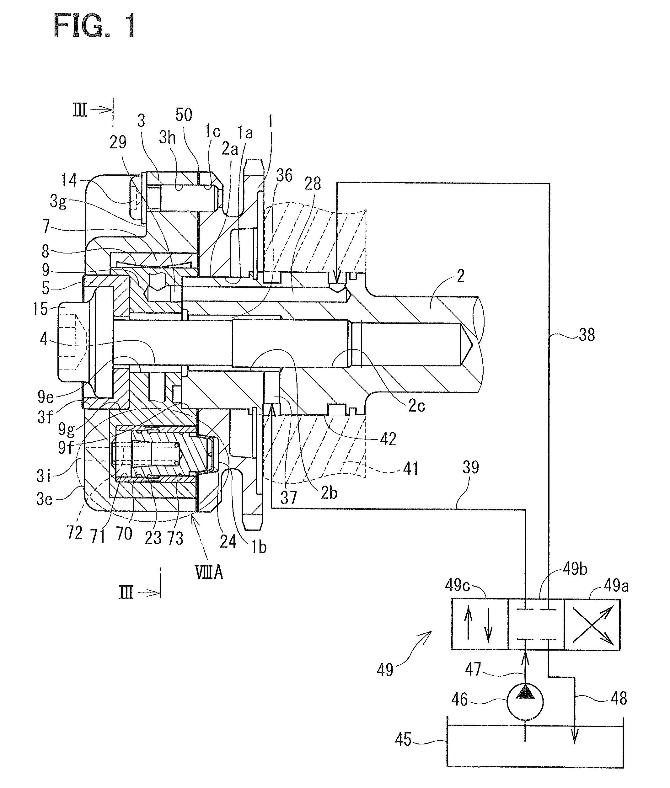
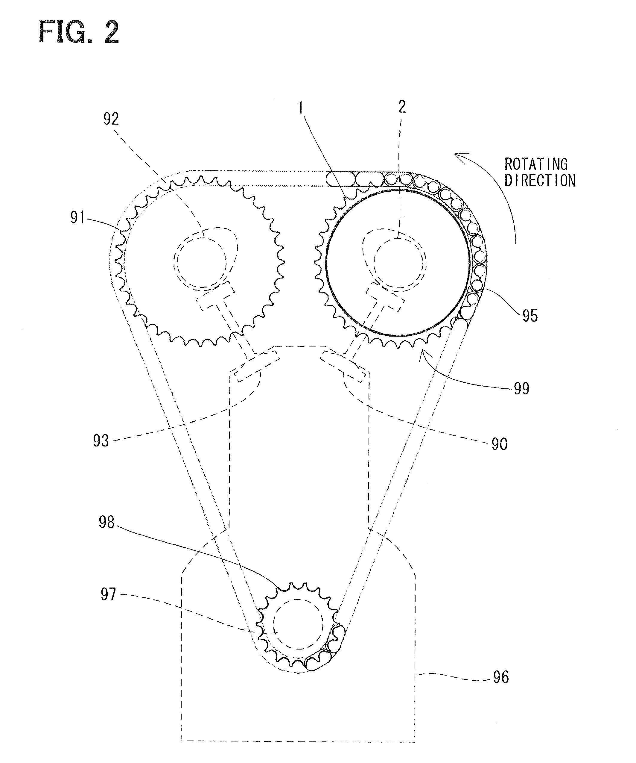
[0022]A first embodiment of the present invention will be explained hereinafter with reference to FIGS. 1 to 8A. As shown in FIG. 2, a valve timing control device 99 is applied to an intake valve 90 of an internal combustion engine 96, and opens or closes the intake valve 90 with a phase difference relative to a crankshaft 97.

[0023]A sprocket 1 is coaxially arranged with a camshaft 2. A gear 91 for an exhaust valve 93 is coaxially arranged with a camshaft 92. A driving gear 98 is coaxially arranged with the crankshaft 97. The camshaft 2 opens and closes the intake valve 90, while the camshaft 92 opens and closes the exhaust valve 93. A chain 95 is engaged with the sprocket 1, the gear 91 for the exhaust valve 93 and the driving gear 98, so as to transmit a driving force of the crankshaft 97 to the sprocket 1 and the gear 91 for the exhaust valve 93 so that those gears are rotated in a synchronized manner with each other.

[0024]The crankshaft 97 may correspond to a driving shaft, and ...

second embodiment

[0112]As shown in FIG. 9, a sealing plate 500 of a second embodiment is produced by applying a sealing material 50s on the surface of the base part 59 of the sealing plate 50 of the first embodiment. The sealing material 50s may be made of nitrile-butadiene rubber (NBR), liquid gasket, molybdenum disulfide coated member or foamed rubber, for example. When the sealing material 50s is applied to the base part 59, in addition to the effect obtained in the first embodiment, the sealing property can be improved on the supporting face of the sealing plate, and the working oil can be more effectively prevented from leaking outside. The sealing material 50s is applied to a face of the base part 59 opposing to the shoe housing 3 or a face of the base part 59 opposing to the sprocket 1, or is applied to both faces of the base part 59 opposing to the shoe housing 3 and the sprocket 1, respectively.

Other Embodiments

[0113]The valve timing control device can be applied not only to the intake valv...


PUM


Abstract

A valve timing control device includes a first housing, a vane rotor, a second housing, a sealing plate, a regulating portion and a biasing portion. The sealing plate is interposed between the first housing and the second housing. The biasing portion biases the regulating portion toward the sealing plate. The sealing plate has a recess recessed from a base part toward the second housing at a predetermined position corresponding to the regulating portion in a relative rotation of the vane rotor. The regulating portion regulates the relative rotation of the vane rotor relative to the first housing and the second housing by being fitted with the recess of the sealing plate.

Description

CROSS REFERENCE TO RELATED APPLICATION[0001]This application is based on Japanese Patent Application No. 2011-5752 filed on Jan. 14, 2011, the disclosure of which is incorporated herein by reference in its entirety.BACKGROUND OF THE INVENTION[0002]1. Field of the Invention[0003]The present invention relates to a valve timing control device.[0004]2. Description of Related Art[0005]A vane-type valve timing control device is known in which a camshaft is driven by a crankshaft of an internal combustion engine via a timing pulley synchronously rotated with the crankshaft and a chain sprocket. At least one of an intake valve and an exhaust valve is opened / closed with a phase difference based on a relative rotation between the camshaft and the timing pulley or the chain sprocket. In the vane-type valve timing control device, a vane rotor having vanes is rotatably accommodated in a housing member, so that axial end surfaces of the vane rotor are in a sliding contact with respective inner su...

Claims


Application Information

Patent Timeline
Patent Type & Authority Patents(United States)
IPC IPC(8): F01L1/34
CPCF01L1/3442F01L2001/34456F01L2001/34469F01L2001/0537F01L2001/34479F01L2250/02
Inventor HAYASHI, MASASHI
Owner DENSO CORP
Features
  • R&D
  • Intellectual Property
  • Life Sciences
  • Materials
  • Tech Scout
  • Unparalleled Data Quality
  • Higher Quality Content
  • 60% Fewer Hallucinations
Learn More