Method of piloting a rotary wing drone having multiple rotors

a technology of rotary wing drones and rotors, which is applied in the direction of toy aircraft, process and machine control, instruments, etc., can solve the problems of not being able to achieve optimal and long flight time, and achieve the effect of reducing the length of flight tim

Inactive Publication Date: 2013-07-02
PARROT
View PDF8 Cites 35 Cited by
  • Summary
  • Abstract
  • Description
  • Claims
  • Application Information

AI Technical Summary

Benefits of technology

[0019]The object of the invention is to propose a method that enables this transition to be managed in a manner that is completely automatic and optimized, i.e. that takes place quickly, along a trajectory that is short, and without any change of sign in the speed of the drone or any oscillation of the drone, and thus in a minimum length of time for reaching the hovering state.

Problems solved by technology

Nevertheless, if the zero target values for speed and for angle of tilt are applied directly as setpoints to the control loop, it is often observed that the drone takes quite a long time to reach the final hovering state after following a path that is long, and often after its speed has changed sign one or more times, i.e. the drone overshoots the fixed point, reverses, oscillates, etc., with this involving a stopping time (i.e. the time taken to reach the final hovering state and as measured from the beginning of the transition) that is not optimum when compared with a situation in which a skilled user directly controls the transition from the moving state to the hovering state.

Method used


Image

  • Method of piloting a rotary wing drone having multiple rotors
  • Method of piloting a rotary wing drone having multiple rotors
  • Method of piloting a rotary wing drone having multiple rotors

Examples


Embodiment Construction

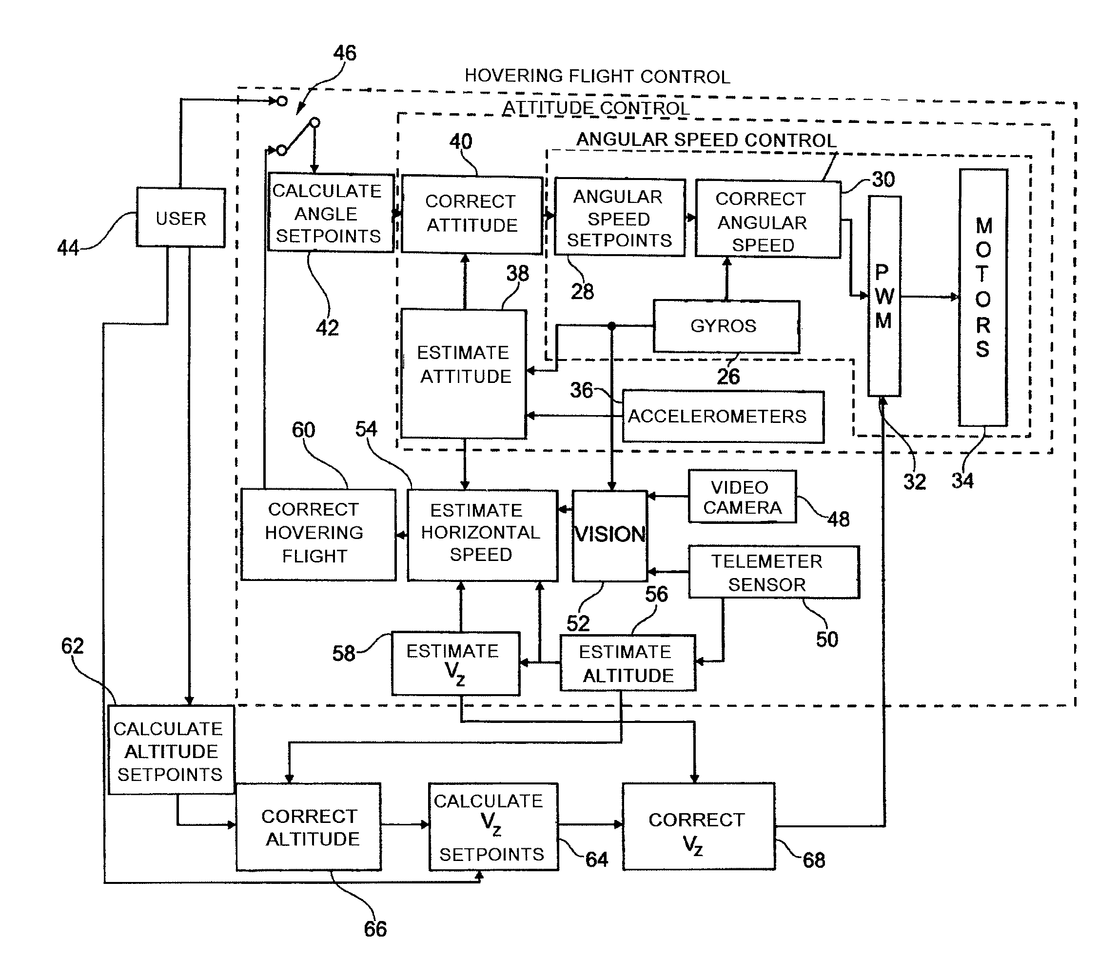
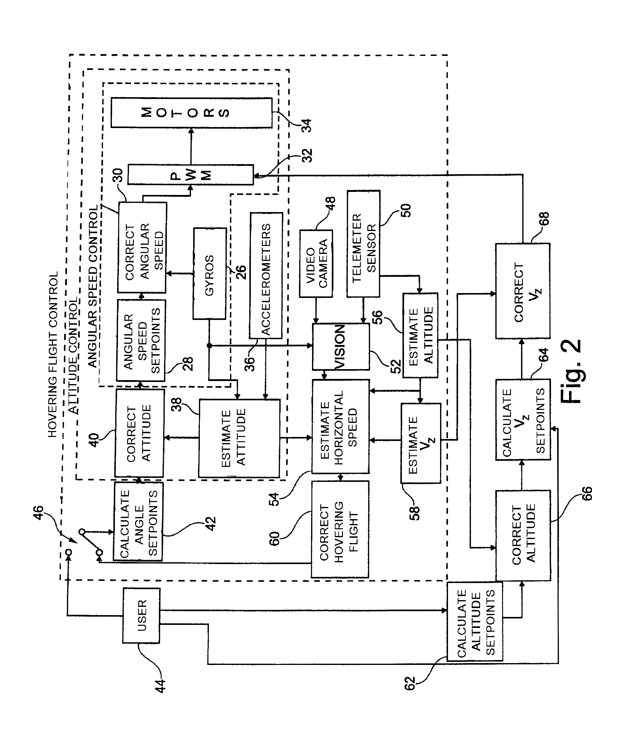
[0040]The implementation of the invention is described below in the context of piloting a quadricopter such as the AR. Drone model from Parrot SA, Paris, France, as described in particular in the above-mentioned WO 2010 / 061099 A2, and in WO 2009 / 109711 A2 (describing an example of a system for automatic stabilization on the basis of information provided by an altimeter and a forward-looking camera), and FR 2 915 569 A1 (describing in particular the gyros and accelerometers used by the drone).

[0041]The drone has four coplanar rotors driven by motors that are controlled independently by an incorporated navigation and attitude control system.

[0042]The drone also includes a front camera giving an image of the scene towards which the drone is heading, and a downwardly-looking camera giving an image of the ground and also used in calculating horizontal speed in translation.

[0043]The drone is controlled by a remote control appliance constituted by an appliance having a touch screen that di...


PUM


Abstract

This method implements a transition from i) moving state in which the drone is flying at speed and tilt angle that are not zero to ii) hovering state in which the drone has speed and tilt angle that are both zero. The method comprises: a) measuring horizontal linear speed, tilt angles, and angular speeds at the initial instant; b) setting stopping time value; c) on the basis of initial measurements and set stopping time, parameterizing a predetermined predictive function that models optimum continuous decreasing variation of horizontal linear speed as a function of time; d) applying setpoint values to a loop for controlling motors of the drone, which values correspond to target horizontal linear speed precalculated from said parameterized predictive function; and e) once hovering state has been reached, activating a hovering flight control loop for maintaining drone at speed and tilt angle that are zero relative to the ground.

Description

FIELD OF THE INVENTION[0001]The invention relates to rotary wing drones such as quadricopters and the like.BACKGROUND OF THE INVENTION[0002]Drones are provided with multiple rotors driven by respective motors that are independently controllable in order to control the drone in attitude and in speed.[0003]A typical example of such a drone is the AR. Drone from Parrot SA, Paris, France, which is a quadricopter fitted with a set of sensors (altimeter, three-axis gyros, accelerometers). The drone also has a front camera picking up an image of the scene towards which the drone is heading, and a downward-looking camera picking up an image of the terrain being overflown.[0004]The drone is controlled by the user by means of a remote control device that is connected to the drone via a radio link.[0005]WO 2010 / 061099 A2 (Parrot SA) in particular describes such a drone and how it can be controlled by means of a telephone or a multimedia player having a touch screen and an accelerometer incorpo...

Claims


Application Information

Patent Timeline
Patent Type & Authority Patents(United States)
IPC IPC(8): B64C13/16B64C27/00
CPCG05D1/0858A63H27/12
Inventor CALLOU, FRANCOIS
Owner PARROT
Why Eureka
Try Eureka