Securing device of a fluid line connection

Active Publication Date: 2013-07-02
CENTTHERM SYSTTECHN
View PDF20 Cites 23 Cited by
  • Summary
  • Abstract
  • Description
  • Claims
  • Application Information

AI Technical Summary

Benefits of technology

The invention provides a simple and cost-effective solution to connect fluid line parts by using a securing device that can be easily fitted and removed. The securing device provides a strong and secure connection that can be easily disconnected. It is designed to be installed without the need for tools and can be visually checked. The securing device is made of a single structural element, reducing material costs and installation time. The internal contour of the clamping body can be designed as a sharp edge or frictional surface to increase the clamping action. The securing device can be manufactured from plastic using a simple production process. The clamping body can also have a web encircling radially on the outside to increase its stability and prevent sliding and folding over under a tensile force.

Problems solved by technology

However, screw connections of this type to a certain extent restrict the flexibility of laying pipes and, furthermore, require time-consuming installation operations.
Said flange leaves or flanges are generally welded to the pipe, this entailing complicated welding operations.
A disadvantage of said sleeve connections is that they are generally not designed to be self-securing and are not designed to withstand tensile forces, and therefore there is the risk, should a tensile loading become effective, of the pipes or fluid line parts which are to be connected sliding apart and releasing the pipe connection or fluid line connection.
It is disadvantageous, however, that visual checking of the securing means in the form of the clamping ring is not possible, since the clamping ring is arranged in the interior of the pipe connection between the pipes and checking is possible only if the pipe connection is released.
The use of a clamping element of this type furthermore has the disadvantage that the clamping element does not immediately come into effect but rather only after a certain starting distance, and therefore the tightness of the connection is not always ensured.
Also, clamping elements of this type, which are generally of elastic design, withstand only a certain tensile force and are not suitable for relatively large tensile loadings.
In particular in the case of pressure-loaded sleeve connections, there is therefore the risk of the sleeve connection becoming released under tensile loading.

Method used


Image

  • Securing device of a fluid line connection
  • Securing device of a fluid line connection
  • Securing device of a fluid line connection

Examples


Embodiment Construction

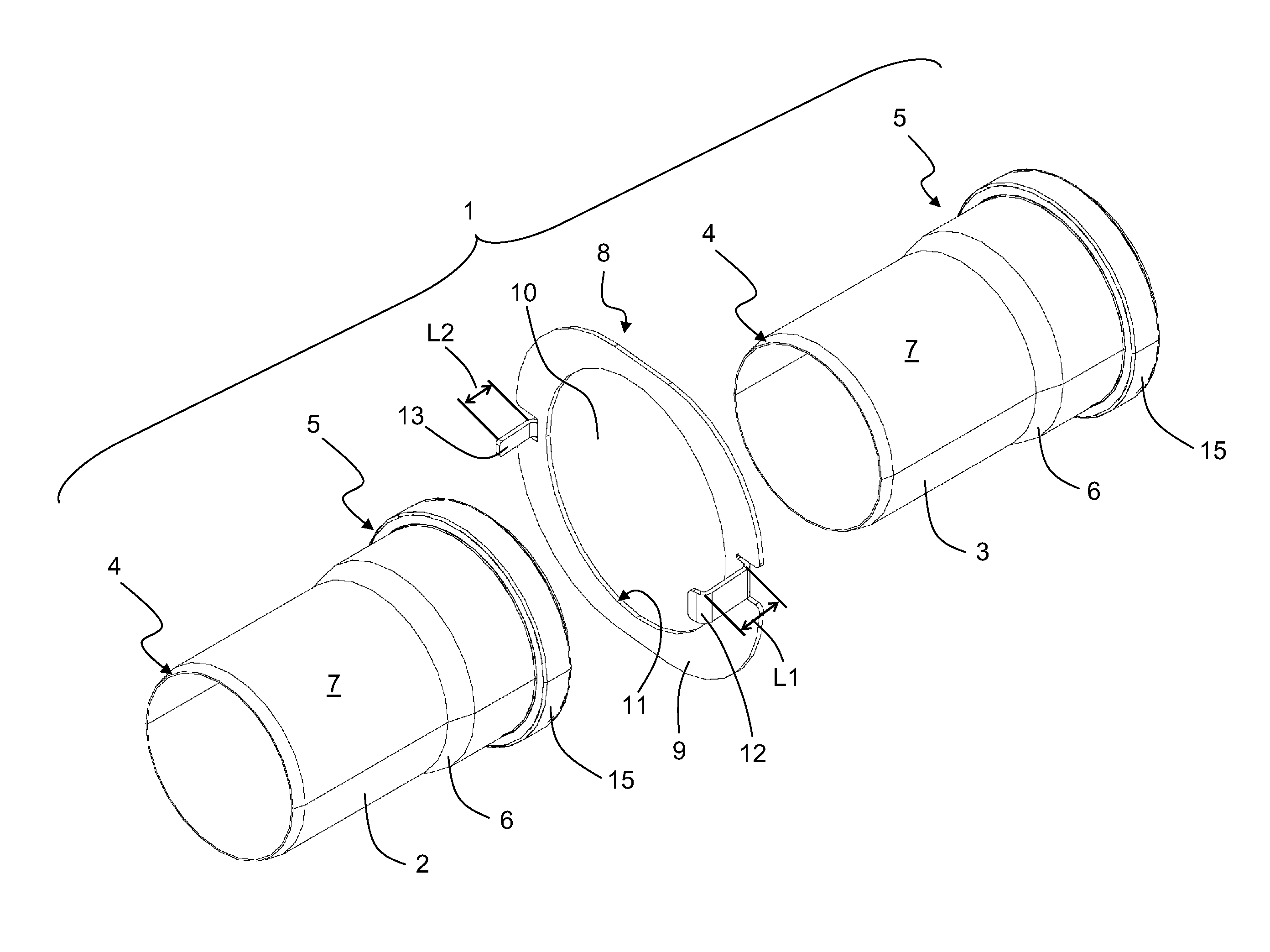
[0035]A pipe connection is described below in the specific exemplary embodiment of the present invention. It goes without saying that the invention is not restricted only to a pipe connection of this type and a securing device fixing said pipe connection but rather connections of any fluid line parts or shaped parts / shaped pieces, such as, for example, pipes, pipe bends, T pieces, Y pieces, sleeves, U pipes, pipe branches, reducing means or reductions, pipe sockets and the like are included.

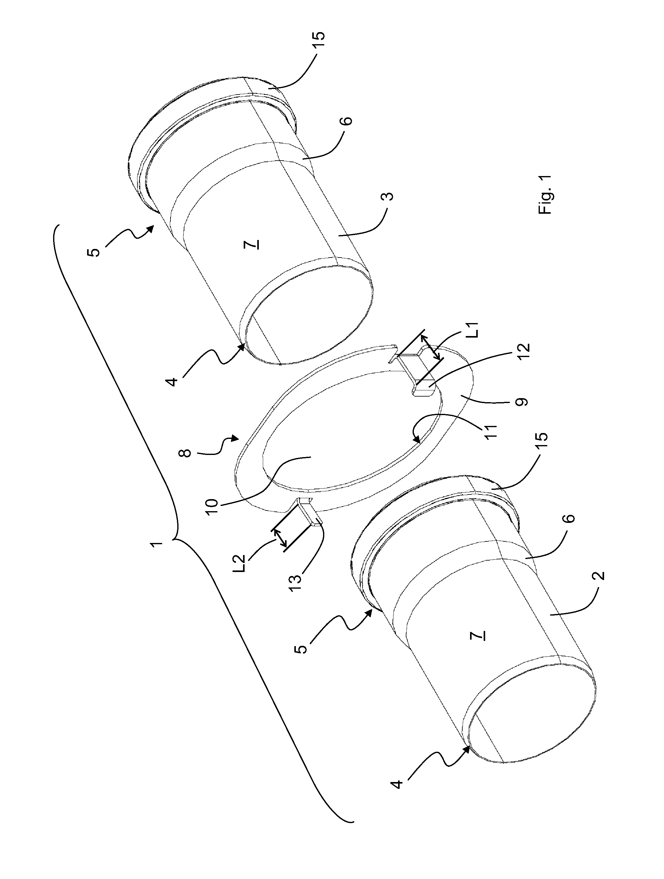
[0036]FIGS. 1 and 5 to 8 show a pipe connection or pipe connection arrangement which is denoted overall by 1 and constitutes the fluid line connection according to the invention. The fluid line connection 1 or pipe connection 1 comprises a first pipe or fluid line part 2 and a second pipe or fluid line part 3 which, in the exemplary embodiment illustrated, are both of circular-cylindrical design and are composed of plastic. An example of a suitable material for the pipes is polypropylene, wherein...


PUM


Abstract

A securing device for axially connecting a sleeve-shaped end section of a first fluid line part to an end section, which is designed as a pointed end, of a second fluid line part includes a clamping body which is of annular design and has a passage opening for insertion of the second fluid line part, at least one retaining element of a hook-shaped design, and at least one spacer of web-shaped design, wherein the at least one retaining element and the at least one spacer are both integrally formed with the clamping body and extend in the same axial direction.

Description

BACKGROUND[0001]The invention relates to a securing device for axially connecting a sleeve-shaped end section of a first fluid line part to an end section, which is designed as a pointed end, of a second fluid line part. Furthermore, the invention relates to a fluid line connection which has a securing device of this type.[0002]In the context of the invention, the expression “fluid line part” comprises all types of tubular shaped pieces or shaped parts in pipelines, such as, for example, pipes, pipe bends, T pieces, Y pieces, sleeves, U pipes, pipe branches, reducing means or reductions, pipe sockets and the like. Embodiments below which relate to pipes, pipelines and pipe connections should therefore not be understood as being restricted to pipes but rather in general to abovementioned types of fluid line parts and the connections thereof. Similarly, the term “fluid” includes both gases and liquids within the meaning of the invention.[0003]It is generally known to connect end secti...

Claims


Application Information

Patent Timeline
IPC IPC(8): F16L21/06
CPCF16B2/246F16L21/08F23J13/04F16L37/08F23J2213/202
Inventor RICHTER, HANS JURGEN
Owner CENTTHERM SYSTTECHN
Why Eureka
Try Eureka