
Structure for mounting an attachment for vehicle

a technology for mounting structures and attachments, applied in vehicular safety arrangments, roofs, bumpers, etc., can solve problems such as unsatisfactory gaps in corner portions of front spoilers, and achieve the effects of reducing the number of mounting steps, increasing the degree of freedom of positional adjustment, and reducing the overall cos

Inactive Publication Date: 2013-07-09
HONDA ACCESS CORP
View PDF19 Cites 0 Cited by
  • Summary
  • Abstract
  • Description
  • Claims
  • Application Information

AI Technical Summary

Benefits of technology

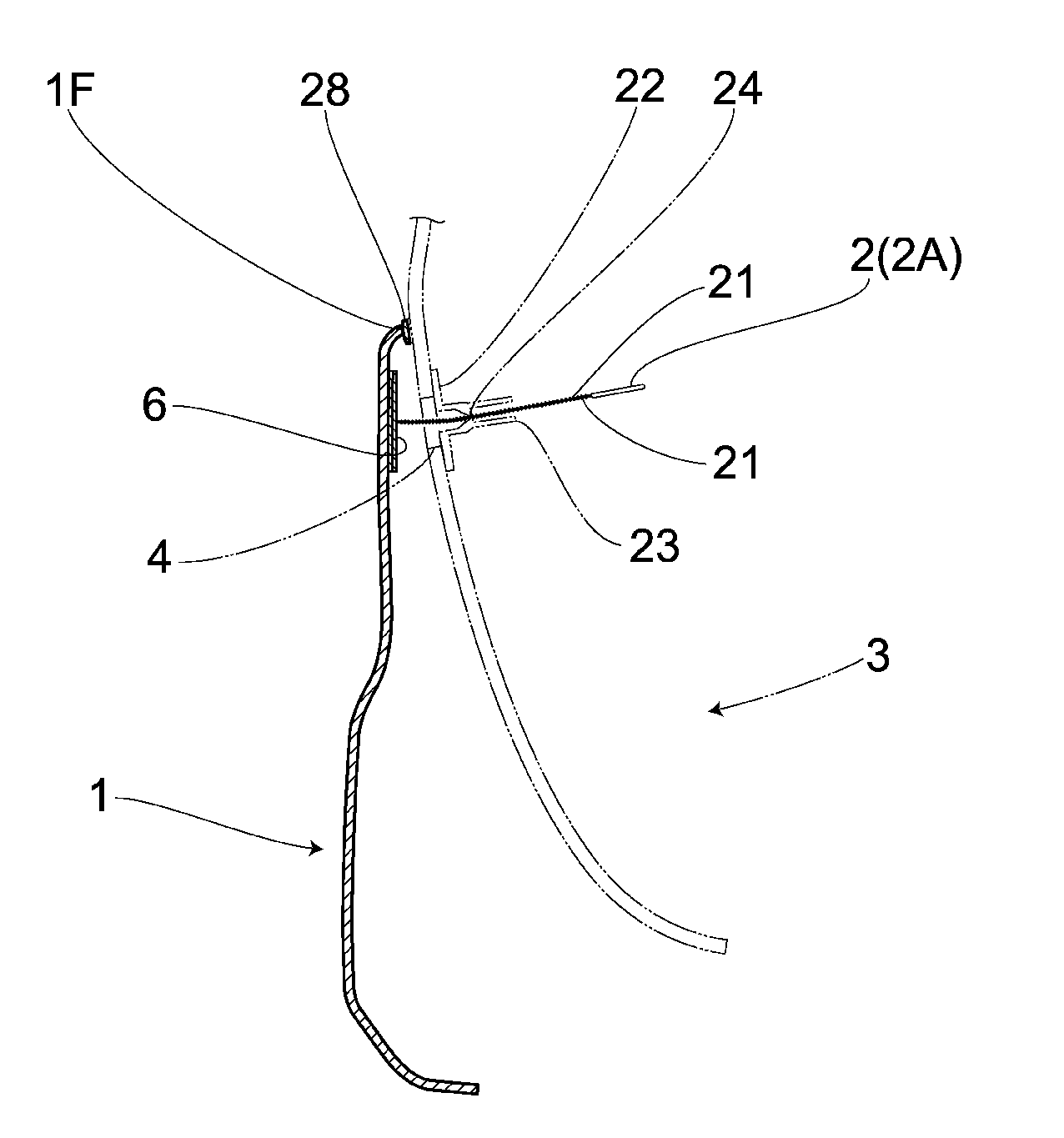
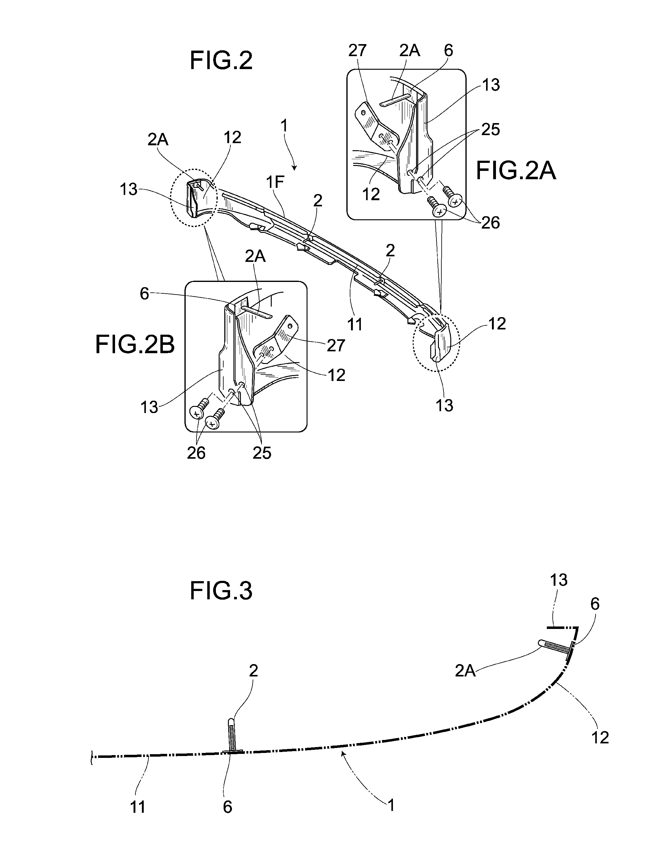
The present invention aims to provide a structure for mounting an attachment for vehicle that can absorb the differences between the attachment and the component being mounted, while reducing the steps and procedures required for mounting. The structure also addresses changes in attachment dimension due to temperature change and enables adjustment of the male clip position to eliminate any undesired space between the attachment and the component. Additionally, the structure allows for the absorption of differences between the attachment and the component, making it easier to mount resin components, such as resin spoilers on resin bumpers. Overall, the structure simplifies attachment manufacturing and mounting, reducing costs and complexity.

Problems solved by technology

With regard to the aforementioned structure for mounting a resin component, an undesired gap may occur in a corner portion of the front spoiler, due to the dimensional differences resulting from the respective forming conditions, etc. of the front spoiler and the front bumper, and due to the imprecise location of an attachment hole, especially since the front spoiler is formed into an elongated shape.

Method used


Image

  • Structure for mounting an attachment for vehicle
  • Structure for mounting an attachment for vehicle
  • Structure for mounting an attachment for vehicle

Examples


second embodiment

[0047]FIGS. 7 and 8 are diagrams illustrating a second embodiment of the present invention, in which same symbols are used to illustrate portions identical to those in the first embodiment. Schematically, the second embodiment includes: strip-shaped male clips 2, 2A, 2B provided on a rear spoiler 31 made of synthetic resin and referred to as the attachment; insertion holes 4 provided on a rear bumper 33 also made of synthetic resin and referred to as the component, the insertion holes 4 being provided for inserting the male clips 2, 2A, 2B therethrough; and female clips 5 to be engaged with the male clips 2, 2A, 2B.

[0048]Said rear bumper 33 is integrally provided with an elongated portion 201 extending toward the left and right thereof, and corner portions 202 provided on the end portion of the elongated portion 201 and referred to as the side edge portion, with the corner portion 202 being formed in a substantially back-to-front direction intersecting the longitudinal direction of ...


PUM


Abstract

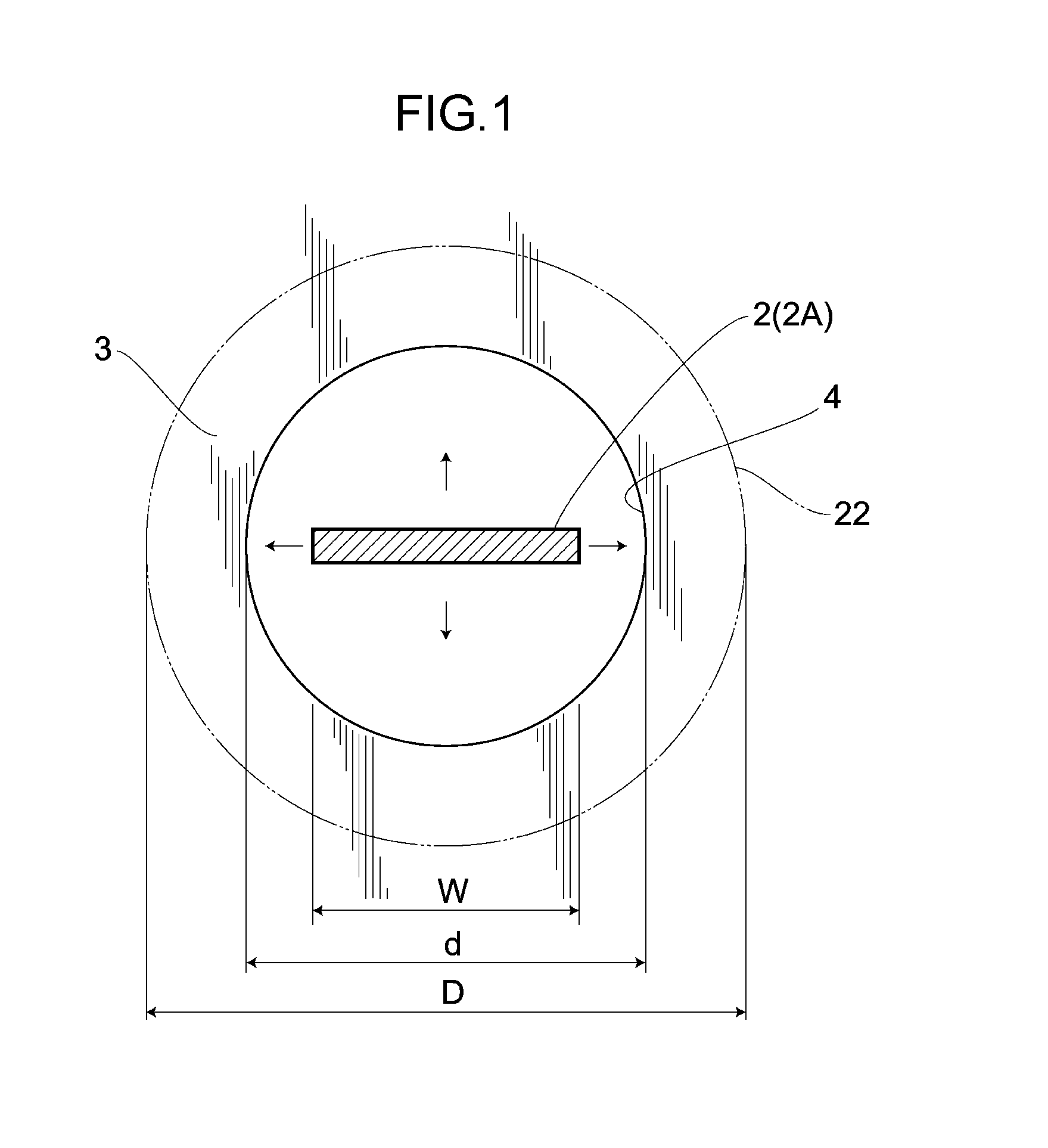
There is provided a structure for mounting an attachment for vehicle capable of absorbing the marginal difference of a front spoiler and reducing the procedures for controlling the dimension of the front spoiler. The structure for mounting a front spoiler on a front bumper includes: a male clip provided on the front spoiler; an insertion hole provided on the front bumper for inserting the male clip therethrough; and a female clip engaged with the male clip and allowing the front spoiler to be held by the front bumper. The male clip is loosely inserted through the insertion hole and engaged with the female clip around the insertion hole via an abutting brim, thereby producing a gap between the insertion hole and the male clip, thus increasing the degree of freedom of positional adjustment, reducing the steps for mounting and controlling the accuracy of the attachment, reducing the overall cost.

Description

BACKGROUND OF THE INVENTION[0001]1. Field of the Invention[0002]The present invention relates to a structure for mounting an attachment on a component already mounted on a vehicle, in particular to a structure for mounting an attachment for vehicle comprising a male clip provided on the attachment, an insertion hole provided on the component for inserting the male clip therethrough, and a female clip engaged with the male clip.[0003]2. Description of Related Art[0004]Conventionally, there has been known a structure for mounting a resin component on a vehicle, in which a resin front spoiler is secured to a resin front bumper by inserting a boss portion protruding from the resin front spoiler into an attachment hole provided in the resin front bumper, and rendering an annular locking ring to abut against a fixing surface of the resin front bumper by putting the annular locking ring on the boss portion on the side opposite to the side on which the boss portion is inserted, as disclosed...

Claims


Application Information

Patent Timeline
Patent Type & Authority Patents(United States)
IPC IPC(8): B62D35/00
CPCB60R19/18B60R19/24F16B5/0628B60R2019/1886B60R2019/247
Inventor MITSUO, KAZUTAKAADACHI, RYOICHITAKADA, JUNSEO, MASANORI
Owner HONDA ACCESS CORP
Learn More