Apparatus for dimensioning circumference of cavity for introduction of a prosthetic implant

a prosthetic implant and apparatus technology, applied in the field of apparatus for dimensioning the circumference of the cavity for the introduction of a prosthetic implant, can solve the problems of deficiency of li device, surgeons may have difficulty distinguishing, and imaging using li device may be negatively affected

Inactive Publication Date: 2013-07-16
REPLICATION MEDICAL
View PDF20 Cites 4 Cited by
  • Summary
  • Abstract
  • Description
  • Claims
  • Application Information

AI Technical Summary

Benefits of technology

[0013]In the collapsed configuration, the deformable member fits within the confines of the lumen. In one embodiment, the deformable member has a width that is about the same width as the lumen. The deformable member is adjustable to a plurality of different intermediate widths measured across the deformable member when the longitudinal member moves distally. The longitudinal member moves the deformable member relative to the body from the collapsed configuration to the expanded configuration to increase the adjustable width of the deformable member. In one embodiment, the longitudinal member pushes the deformable member out of the lumen and causes the deformable member to expand as it exits the lumen. In one embodiment, the proximal end portion of the longitudinal member contains one or more markings which correspond to predetermined circumference amounts of the deformable member. The proximal end portion of the longitudinal member extends past the end of the lumen so the markings can be observed at a suitable distance from the site of the surgical entry.
[0015]According to another embodiment of the present disclosure, there is provided device for dimensioning a circumference of a cavity. The device includes a body forming a lumen having a distal aperture and a longitudinal member extending through the lumen with a distal end and a proximal end. The longitudinal member is capable of slidable movement through the body between retracted and advanced positions. The device also has a flexible member adapted to conform to a circumference of an intervertebral disc space. The flexible member is operatively connected to the longitudinal member such that upon retraction of the longitudinal member, the flexible member retracts into the lumen. When the longitudinal member is moved toward the advanced position the flexible member is advanced out of the lumen and expands to conform to a dimension which is limited by and approximates the circumference of the intervertebral disc space. The device also has the longitudinal member with a proximal end with at least one marking. The marking corresponds to a predetermined circumference of a prosthetic implant. When the longitudinal member is advanced from the retracted configuration to the expanded configuration, a flexible member circumference expands to contact a lateral side wall of the cavity. The flexible member circumference upon contacting the lateral side wall of the cavity may correspond to the marking on the proximal end of the longitudinal member. The marking corresponds to the predetermined prosthetic implant circumference when the predetermined prosthetic implant is at its maximum diameter, e.g., when hydrated. Visualization of the marking indicates that the circumferential dimension of the cavity is sufficient to accommodate the circumferential dimension of the prosthetic implant and thus provide a proper fit within the cavity.
[0017]According to another embodiment of the present disclosure, there is provided a kit for use in implanting a prosthetic implant. The kit includes an access member referred to herein as a working tube. The working tube has a first member and a second member which are pivotally attached to each other. In one embodiment, the first and second members are pivotally attached to one another by a first pivot and a second pivot. The first member and second member have first and second respective distraction ends which cooperate by virtue of the pivotal attachment to form a vertebral distractor. The first member is brought into approximation with the second member for distracting a disc space at the distraction end. The first member and the second member form a lumen therebetween when brought into approximation. The kit also includes a spreader configured to be inserted into the lumen. The spreader has a distal end configured to assist in maintaining the distracted disc space. The kit further includes a closing tube configured to be introduced in coaxial alignment over the working tube. The closing tube prevents the opening of the working tube and confines movement of the first member and the second member to the approximated position. The spreader may be removed when the closing tube is disposed in coaxial alignment with the working tube.

Problems solved by technology

Although potentially useful, the Li device is deficient.
However, such imaging using Li's device may be negatively affected by the presence of other elements, e.g., actuator, engagement member, and / or plates, in addition to the first flexible element which obscure the image, i.e., the surgeon may have difficulty distinguishing between the flexible element, the plates, the actuator and the engagement member in determining the size of the blind void.
Additionally, Li's device has a relatively large profile, and a thick width which may prove cumbersome More importantly, the second flexible element would not function within the confines of a narrow cannula since it would be unable to bulge against the side walls of the cannula.
The cannula would then be reintroduced for additional spinal procedures, which is inefficient.
Li's device is not well-suited for precisely determining the size the blind void for a pre-dimensioned prosthetic implant in an efficient manner.
The process may take extra time and requires multiple measurements.

Method used


Image

  • Apparatus for dimensioning circumference of cavity for introduction of a prosthetic implant
  • Apparatus for dimensioning circumference of cavity for introduction of a prosthetic implant
  • Apparatus for dimensioning circumference of cavity for introduction of a prosthetic implant

Examples


Embodiment Construction

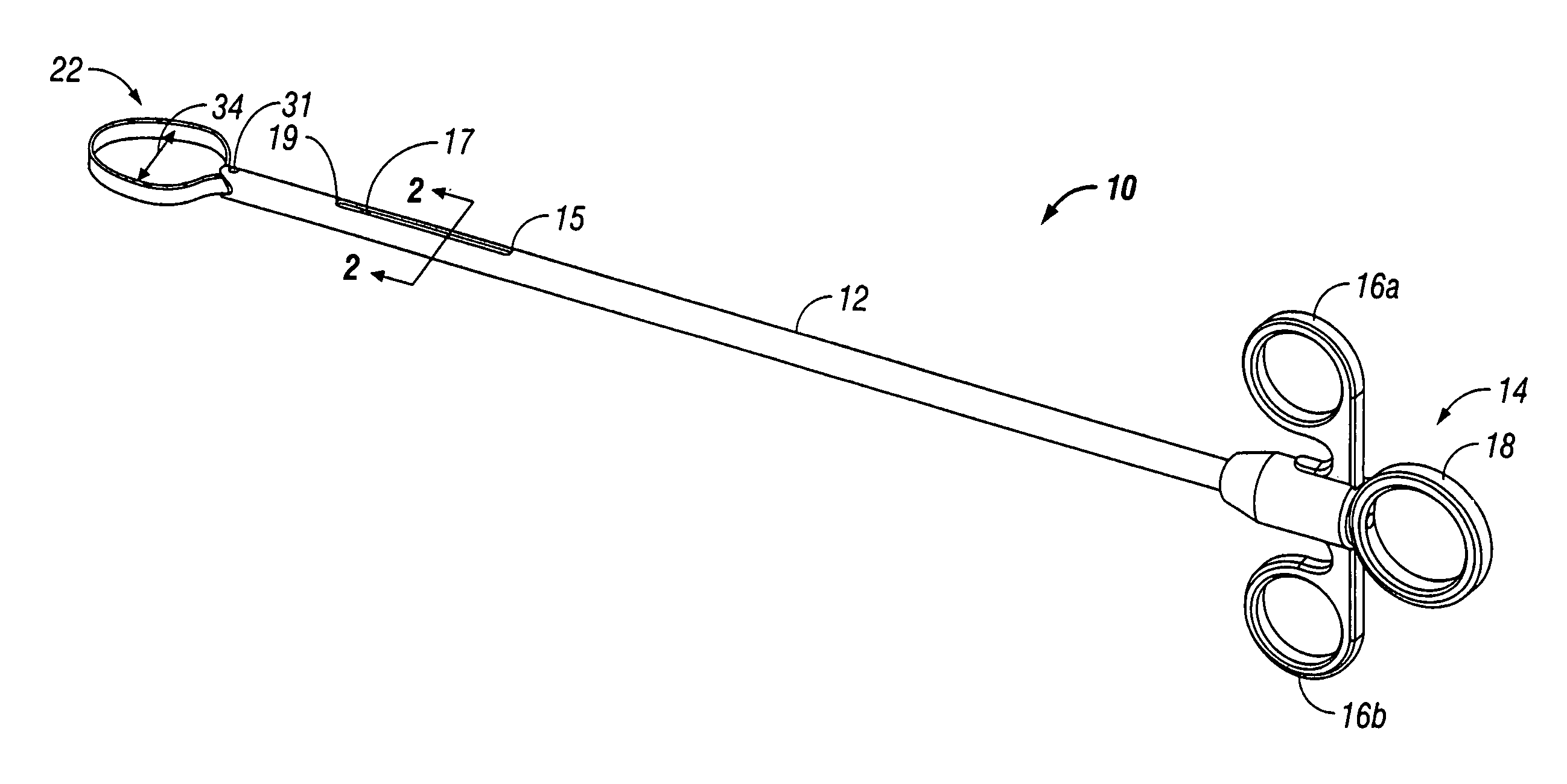
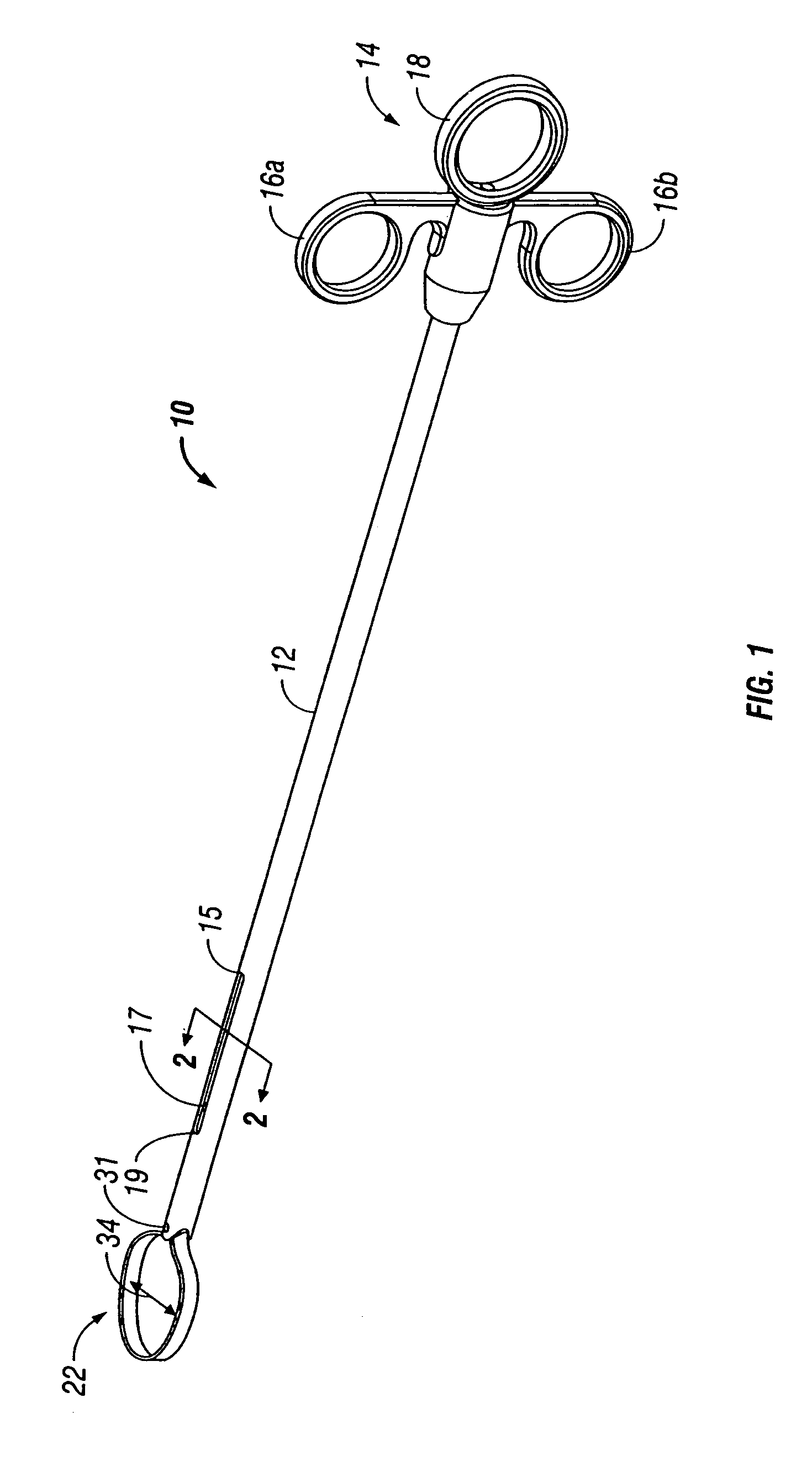
[0043]Embodiments of the presently disclosed device will be described herein below with reference to the accompanying drawing figures wherein like reference numerals identify similar or identical elements. In the following description, well-known functions or constructions are not described in detail to avoid obscuring the disclosure in unnecessary detail. It should be understood that, as used herein, the terms “circumference” and “circumferential” are used in their customary manner, e.g., referring to the boundary of a circle, but are also intended to encompass ellipsoid and rectangular configurations which may have regular or irregular topography. This broad reading of the terms “circumference” and “circumferential” is meant to take into account the fact that cavities which result from cavitation procedures or natural processes can have irregular shapes. The circumference of such cavities can be measured in accordance with the present disclosure.

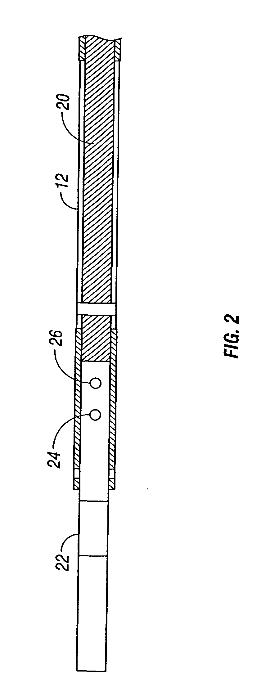
[0044]Referring now to FIG. 1, ther...


PUM


Abstract

A device for dimensioning a circumference of a cavity includes a body with a lumen and a distal aperture. The device also includes a longitudinal member extending through the lumen with a distal end and a proximal end. The longitudinal member is capable of slidable movement through the body between retracted and advanced positions. The device also includes a flexible member adapted to conform to a circumference of a cavity contained, e.g., in an intervertebral disc space. The flexible member is operatively connected to a longitudinal member such that upon retraction of the longitudinal member the flexible member retracts into the lumen. When the longitudinal member is moved toward the advanced position, the flexible member is advanced out of the lumen and expands to conform to a dimension which approximates the circumference of the cavity. An apparatus is provided which includes a device for dimensioning a circumference of a cavity and an access member for facilitating conduction of the device to a surgical site, the device adapted and configured to fit within the access member. A kit is provided which includes a working tube incorporating a vertebral distractor, a spreader for assisting and maintaining the vertebral distractor in a distracted configuration, a closing tube for maintaining the working tube in a closed configuration, and a cavity circumference measuring device.

Description

CROSS REFERENCE TO RELATED APPLICATIONS[0001]The present application claims the benefit and priority of provisional application Ser. No. 60 / 874,618 filed on Dec. 13, 2006 and titled APPARATUS FOR DIMENSIONING CIRCUMFERENCE OF CAVITY FOR INTRODUCTION OF A PROSTHETIC IMPLANT. The entire contents of Ser. No. 60 / 874,618 are hereby incorporated in its entirety herein.BACKGROUND[0002]1. Technical Field[0003]The present disclosure is directed to a device for determining a circumference of a cavity such as a spinal disc cavity post nucleotomy. More particularly, the present disclosure is directed to a device for determining whether the cavity is dimensionally sufficient to receive a prosthetic implant.[0004]2. Description of the Related Art[0005]Applications are known in the art which create interior disposed cavities of unknown dimensions associated with herniated discs. A device for determining parameters of blind voids is described in the art. See, e.g., U.S. Pat. No. 6,500,132 B1 to Li ...

Claims


Application Information

Patent Timeline
Patent Type & Authority Patents(United States)
IPC IPC(8): A61B17/60A61F2/00
CPCA61F2/4657A61F2002/444A61F2002/4658A61F2002/4659
Inventor GEISERT, CHRISTOPHEKUFELD, EDUARD
Owner REPLICATION MEDICAL
Why Eureka
Try Eureka