Automotive headlamp apparatus controlling light distribution pattern

a headlamp and pattern technology, applied in lighting and heating apparatus, signalling/lighting devices, vehicle components, etc., can solve the problems of providing glare to the drivers of other vehicles, the possibility that the oncoming vehicle may be turning on a headlamp, etc., to reduce the illuminance of an individual pattern, increase the illuminance of at least one, and improve the visibility of the driver

Active Publication Date: 2013-07-16
KOITO MFG CO LTD
View PDF11 Cites 6 Cited by
  • Summary
  • Abstract
  • Description
  • Claims
  • Application Information

AI Technical Summary

Benefits of technology

[0009]The present invention has been made based on such a recognition by the present inventor, and one of the purposes of the invention is to provide a technique in which, when controlling emission of light in accordance with presence of a forward vehicle, the visibility of a driver in an area where a forward vehicle is not present can be further enhanced.
[0010]In order to solve the aforementioned problem, an automotive headlamp apparatus according to an embodiment of the present invention comprises: a lamp unit configured to be capable of forming an additional light distribution pattern that includes an upper area above the cut-off line of a light distribution pattern for low beam and that is divided into a plurality of individual patterns; and a controller configured to control formation of each of the individual patterns in accordance with presence of a forward vehicle, in which the controller reduces the illuminance of an individual pattern overlapping an area where a forward vehicle is present and increases the illuminance of at least one of other individual patterns.

Problems solved by technology

Although the high beam is excellent in the visibility by a driver in comparison with the low beam, there is the problem of providing glare to the drivers of other vehicles.
That is, when the aforementioned emission-prohibited object is an oncoming vehicle, there is the possibility that the oncoming vehicle may be turning on a headlamp.

Method used


Image

  • Automotive headlamp apparatus controlling light distribution pattern
  • Automotive headlamp apparatus controlling light distribution pattern
  • Automotive headlamp apparatus controlling light distribution pattern

Examples


embodiment 1

(Embodiment 1)

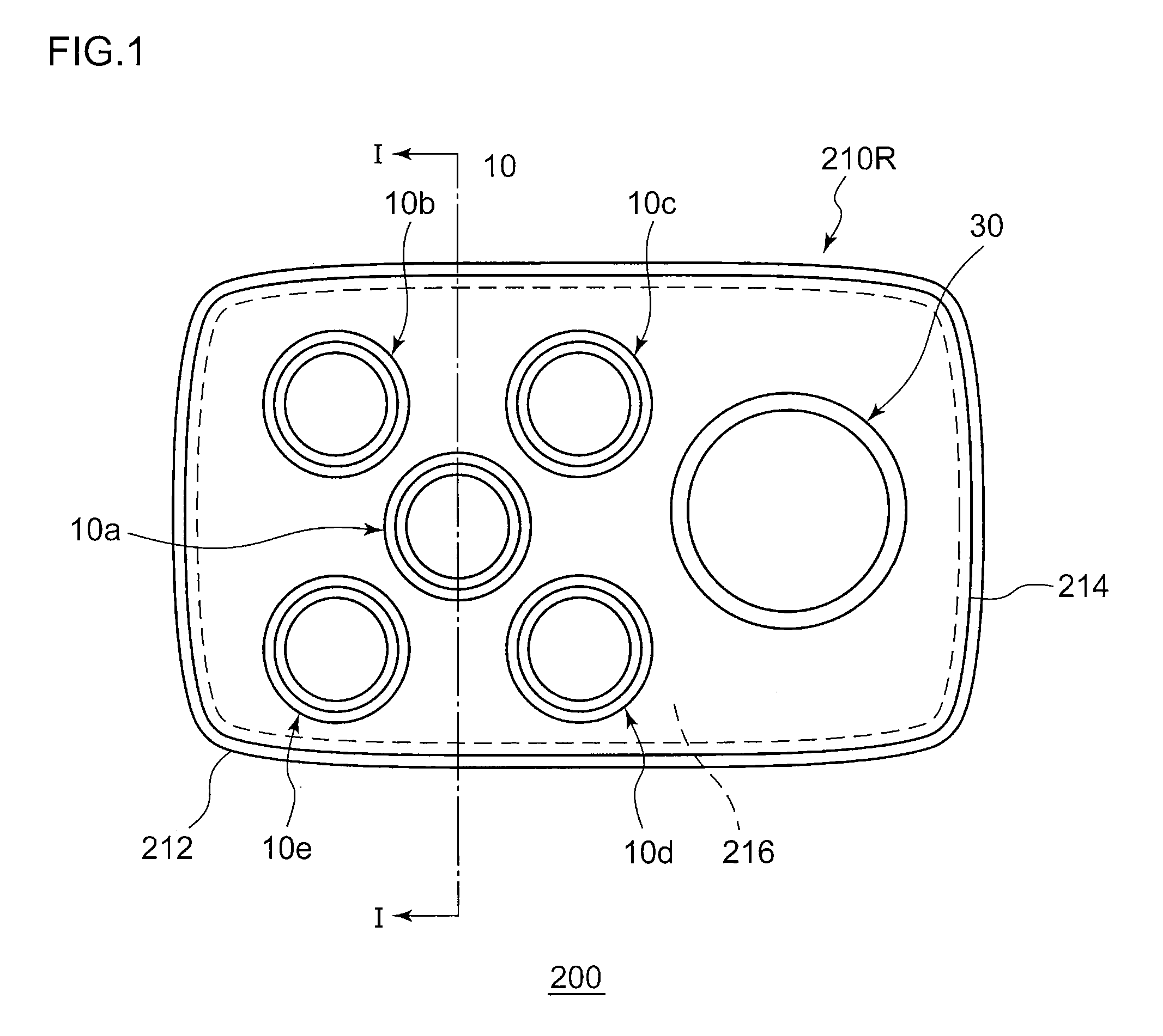
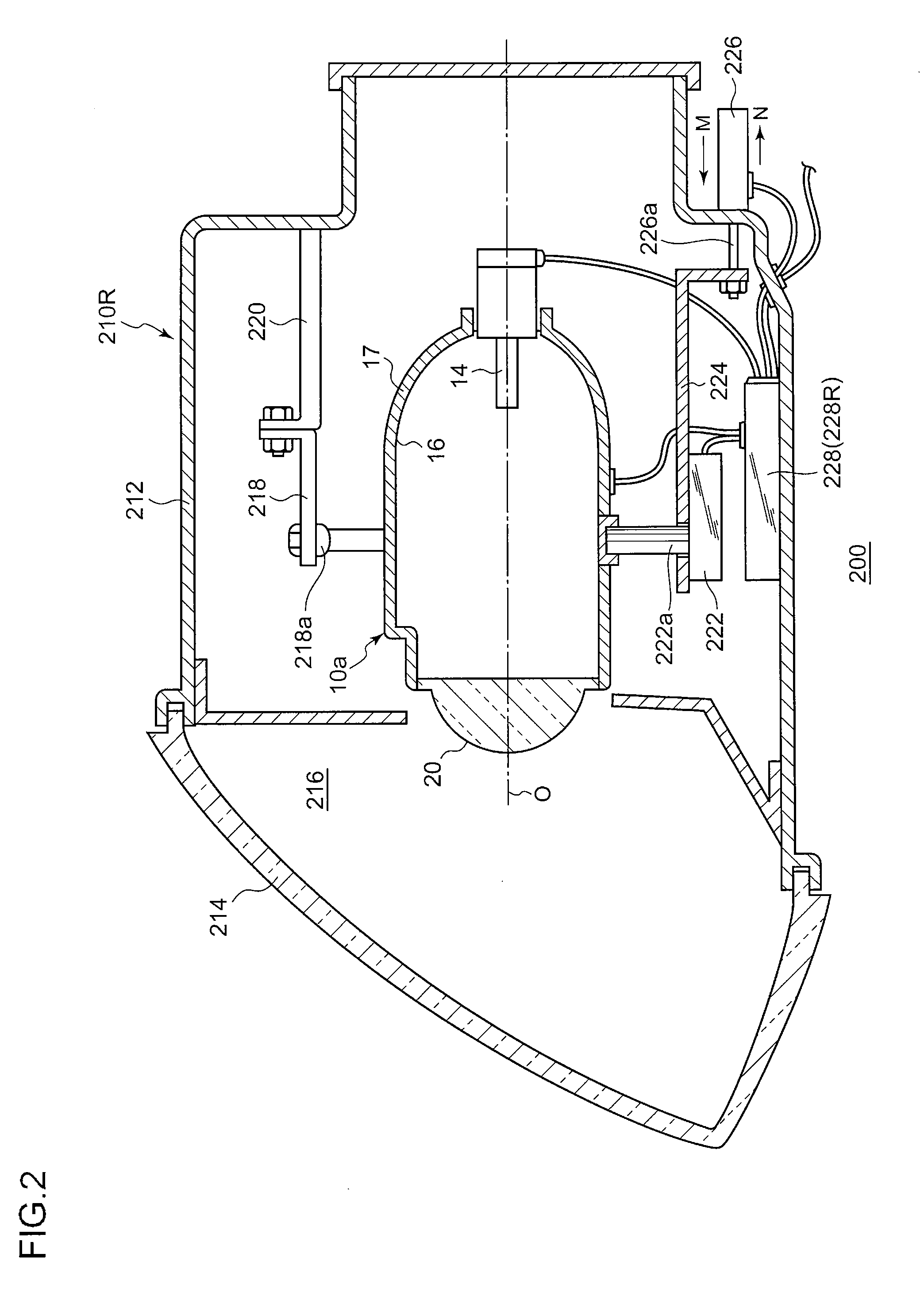
[0024]FIG. 1 is a schematic front view of an automotive headlamp apparatus according to Embodiment 1. An automotive headlamp apparatus 200 according to the present embodiment is a light distribution variable headlamp whose headlamp unit is singly arranged on each side of the vehicle width direction. The headlamp units arranged on both sides have the structures substantially the same to each other, other than that both structures are symmetrical to each other. Accordingly, in the following descriptions, the structure of the headlamp unit 210R, arranged on the right side, will be described and descriptions with respect to the headlamp unit on the left side will be appropriately omitted. It is noted that, when each component of the headlamp unit on the left side is described, for convenience of explanation, each component will be denoted with the same reference numeral as that of the corresponding component of the headlamp unit 210R.

[0025]The headlamp unit 210R has a lamp...

embodiment 2

(Embodiment 2)

[0063]An automotive headlamp apparatus according to Embodiment 2 performs the control in which the illuminance of the individual pattern overlapping an area where high visibility is demanded, the area being determined in accordance with the driving road of the driver's vehicle, of the individual patterns overlapping an area where a forward vehicle is not present. Hereinafter, the present embodiment will be described. Because the major structure of an automotive headlamp apparatus and the shapes of light distribution patterns that can be formed, etc., are similar to those in Embodiment 1, similar structures to those in Embodiment 1 will be denoted with the same reference numerals and the descriptions and illustrations with respect to them will be appropriately omitted.

[0064]FIG. 9 is a view for illustrating a light distribution pattern in an automotive headlamp apparatus according to Embodiment 2, when a forward vehicle has been detected. In an automotive headlamp appar...


PUM


Abstract

An automotive headlamp apparatus comprises: a lamp unit configured to be capable of forming an additional light distribution pattern that includes an upper area above the cut-off line of a light distribution pattern for low beam and that is divided into a plurality of individual patterns; and a controller configured to control formation of each of the individual patterns in accordance with presence of a forward vehicle. The controller reduces the illuminance of an individual pattern overlapping an area where a forward vehicle is present and increases the illuminance of at least one of other individual patterns.

Description

CROSS-REFERENCE TO RELATED APPLICATION[0001]This application is based upon and claims the benefit of priority from the prior Japanese Patent Application No. 2009-167178, filed on Jul. 15, 2009, the entire content of which is incorporated herein by reference.BACKGROUND OF THE INVENTION[0002]1. Field of the Invention[0003]The present invention relates to an automotive headlamp apparatus, and in particular, to an automotive headlamp apparatus used in an automobile, etc.[0004]2. Description of the Related Art[0005]An automotive headlamp apparatus can generally switch low beam and high beam to each other. The low beam illuminates a near distance with a predetermined illuminance so as not to provide glare to forward vehicles including oncoming vehicles and leading vehicles, and is used mainly when driving in an urban area. On the other hand, the high beam illuminates a forward wide area and a remote distance with a relatively high illuminance, and is used mainly when driving at high speed...

Claims


Application Information

Patent Timeline
Patent Type & Authority Patents(United States)
IPC IPC(8): B60Q1/04
CPCB60Q1/1423B60Q2300/054B60Q2300/056B60Q2300/45B60Q2300/332B60Q2300/41B60Q2300/42B60Q2300/322F21S41/663
Inventor TANI, KENTAROSATO, NORIKOKOMATSU, MOTOHIROTANAKA, HIDETADAISHIDA, HIROYUKIUCHIDA, NAOKIKOTAJIMA, TAKUYA
Owner KOITO MFG CO LTD
Why Eureka
Try Eureka