Display panel and display device

a display panel and display technology, applied in the field of display technology, can solve the problems of low reflectivity of a polarizer attached to a display region, difficult for viewers to see the light spot high brightness of an image displayed on the display panel, so as to increase the transmittance of the first polarizer 122, increase the brightness and viewing angle, and increase the specific light irradiated to the light conversion layer 13

Pending Publication Date: 2022-01-13
HUIZHOU CHINA STAR OPTOELECTRONICS TECHNOLOGY CO LTD
View PDF0 Cites 0 Cited by
  • Summary
  • Abstract
  • Description
  • Claims
  • Application Information

AI Technical Summary

Benefits of technology

[0073]It should be explained that the brightness of the indicating light emitted by the light conversion layer 13 is related to an intensity of the specific light irradiated on the light conversion layer 13. The intensity of the specific light irradiated to the light conversion layer 13 is increased by increasing the transmittance of the first polarizer 122 for the specific light.
[0074]It should be explained that the first polarizer 122 can exclude the shielding material for the specific light, so that the transmittance of the specific light on the first polarizer 122 is higher.
[0075]In an embodiment, the second polarizer 112 is a wide-viewing-angle polarizer to increase the brightness and viewing angles of the display panel 10, so that in the meeting scene or the teaching scene, and the display panel 10 has better large-view visibility to realize meeting interaction.

Problems solved by technology

However, a brightness of an image displayed on the display panel is high, and reflectivity of a polarizer attached to a display region is low.
When a laser pointer is used to indicate the display region of the display panel, a brightness of a light spot formed on the display panel by a light beam emitted by the laser pointer is relatively low, which makes it difficult for viewers to see the light spot on the display panel.
In current organic light-emitting diode (OLED) display panels, grooves need to be formed by multiple photomasks, and an overall process flow is relatively long, and costs are relatively high.

Method used


Image

  • Display panel and display device
  • Display panel and display device
  • Display panel and display device

Examples


Embodiment Construction

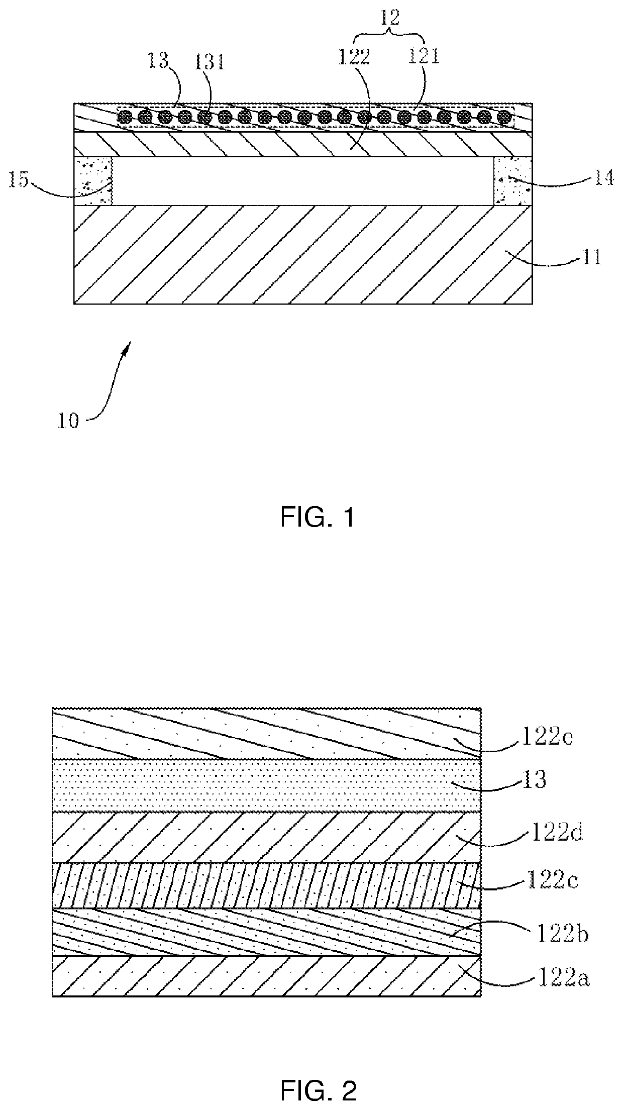
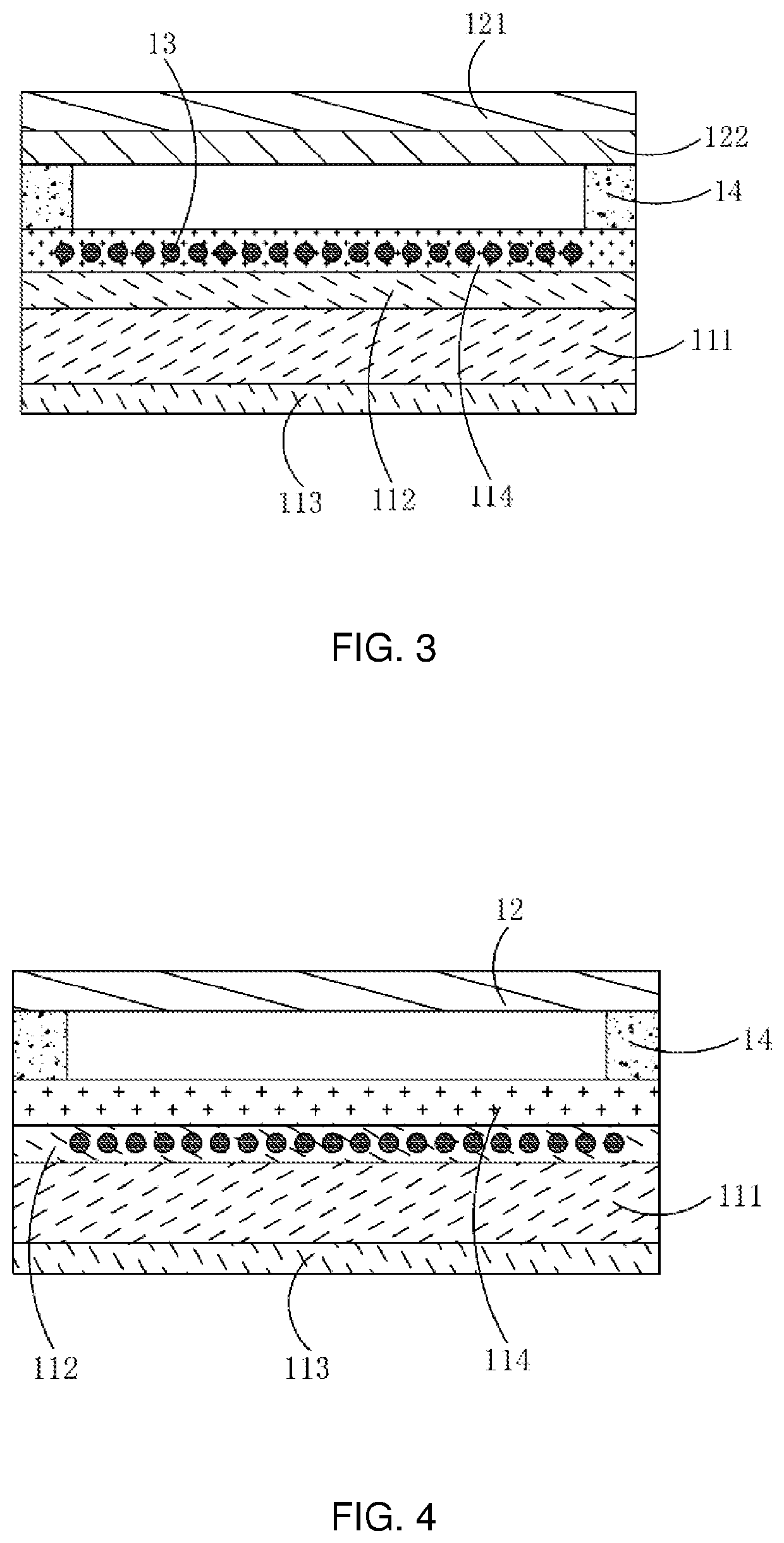
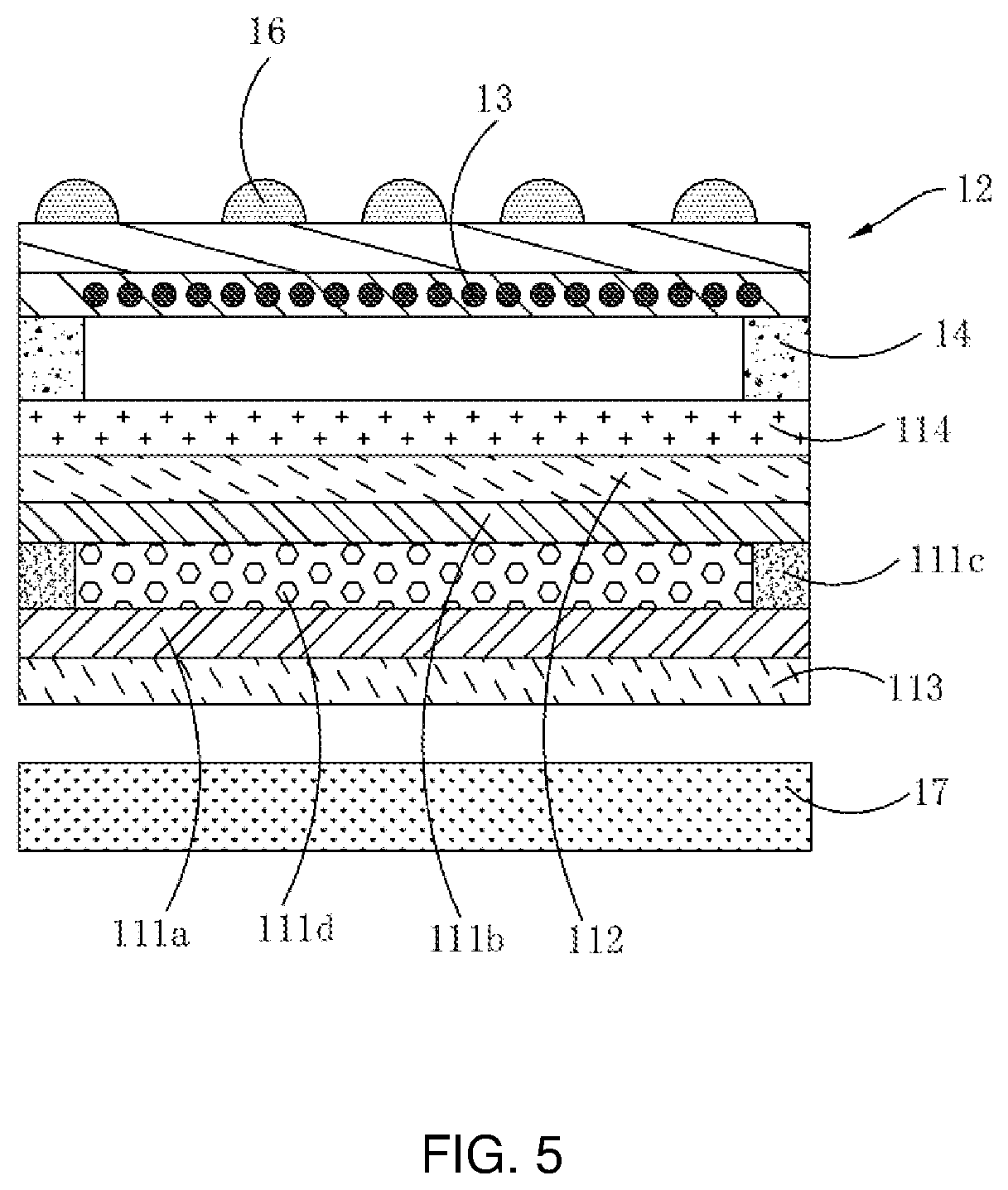
[0040]Examples are described below with reference to the appended drawings, and the drawings illustrate particular embodiments in which the present application may be practiced. Directional terms mentioned in the present application, such as upper, lower, front, rear, left, right, in, out, side, etc., only refer to directions in the accompanying drawings. Thus, the adoption of directional terms is used to describe and understand the present application, but not to limit the present application. In the drawings, units of similar structures are using the same numeral to represent.

[0041]The present application addresses technical problems in current display panels that a brightness of an image displayed on the display panel is high, and reflectivity of a polarizer attached to the display region is low. When a laser pointer is used to indicate a display region of the display panel, a brightness of a light spot formed on the display panel by a light beam emitted by the laser pointer is r...


PUM

PropertyMeasurementUnit
wavelengthaaaaaaaaaa
brightnessaaaaaaaaaa
transmittanceaaaaaaaaaa

Abstract

The present application discloses a display panel and a display device. The display panel includes a display module and an encapsulation cover plate disposed on a light-emitting side of the display module. The light-emitting side of the display module is further provided with a light conversion layer configured to emit indicating light when receiving specific light. The light conversion layer includes a light conversion material. The indicating light is visible light, and a brightness of the indicating light is greater than a determined brightness.

Description

FIELD OF INVENTION[0001]The present application is related to the field of display technology, and specifically, to a display panel and a display device.BACKGROUND OF INVENTION[0002]Large-size display panels are widely used in commercial displays, such as conference all-in-one machines and electronic whiteboards, and have a broad market demand. In teaching, lectures, and other occasions, when a display panel is used to display related presentations, beam emitters such as laser pointers are used to indicate the presentation on the display panel to enhance a presentation effect.[0003]However, a brightness of an image displayed on the display panel is high, and reflectivity of a polarizer attached to a display region is low. When a laser pointer is used to indicate the display region of the display panel, a brightness of a light spot formed on the display panel by a light beam emitted by the laser pointer is relatively low, which makes it difficult for viewers to see the light spot on ...

Claims


Application Information

Patent Timeline
Patent Type & Authority Applications(United States)
IPC IPC(8): G02F1/1339G02F1/1333G02F1/1335G02F1/13357
CPCG02F1/1339G02F1/13338G02F1/133617G02F1/133504G02F1/133531G02F1/1335G09F9/35G09F9/30G02F2203/03G02F1/133331G02F1/1333G02F1/1336G02F1/133562
Inventor HUANG, DONGCHENCHENG, CHINGYUAN
Owner HUIZHOU CHINA STAR OPTOELECTRONICS TECHNOLOGY CO LTD
Why Eureka
Try Eureka