Non-Reflective Optical Connections in Laser-Based Photoplethysmography

Inactive Publication Date: 2012-11-15
KESTREL LABS
View PDF15 Cites 19 Cited by
  • Summary
  • Abstract
  • Description
  • Claims
  • Application Information

AI Technical Summary

Benefits of technology

[0021]In accordance with one embodiment a light delivery apparatus for a photoplethysmographic device comprises a light guide comprising a series of two or more optical elements conducting laser light wherein the two or more elements are coupled together by a non-reflective coupling. Accordingly, several advantages of one or more aspects are as follows: that a minimum of light exiting one optical element in the light guide and entering the next consecutive elemen

Problems solved by technology

The use of one or more lasers in photoplethysmography creates some unique challenges.
When using one or more lasers as light sources, or emitters, in a photoplethysmographic device, the lasers often cannot be placed in the sensor that is positioned in close proximity to, or directly on, the tissue-under-test, as has been typical with LED based photoplethysmographic sensors.
This might be due to the physical size of the laser device being too large for placement in a small sensor designed for application to commonly-used sensing sites such as a finger.
It also might be due to the need to position the laser in close proximity to its driver electronics, to one or more heat sinks, or to other electro-mechanical devices that, as a whole, create a package that is too large or cumbersome to place in the sensor or to conveniently position in immediate proximity to the tissue-under-test.
None of these 
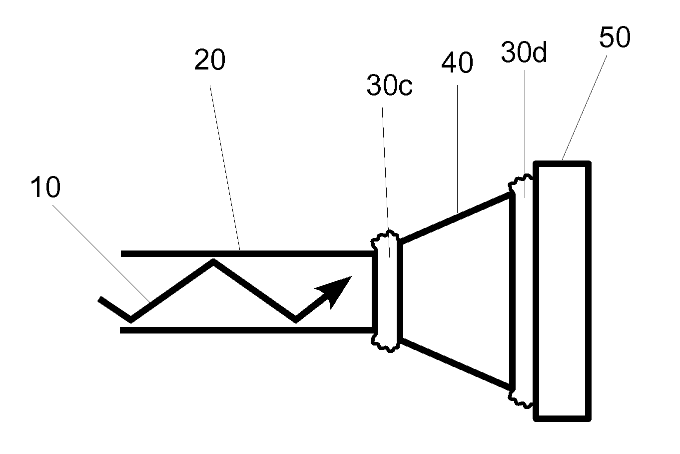
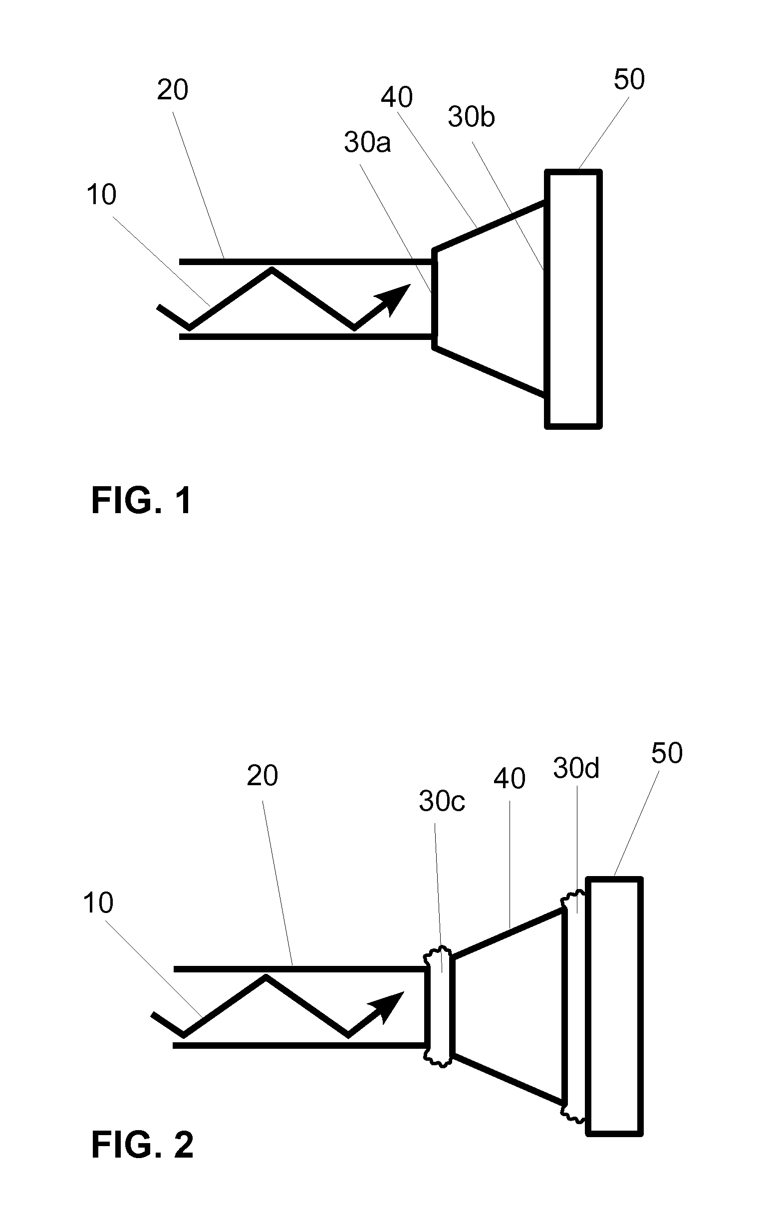
light guide-based devices, however, addressed the problems associated with the instabilities caused by a portion of the light incident on the light guide reflecting back toward the emitter, and in specific, a laser-based emitter.
Back reflections of this magnitude can cause several adverse effects, any one of which can be detrimental to the accuracy of a photoplethysmographic measurement technology that is using laser light sources.
These detrimental effects occur because the light reflected off the surface of the light guide can re-enter the laser cavit

Method used


Image

  • Non-Reflective Optical Connections in Laser-Based Photoplethysmography
  • Non-Reflective Optical Connections in Laser-Based Photoplethysmography

Examples


Example

[0024]One embodiment of a light delivery apparatus for a photoplethysmographic device is shown in FIG. 1. Laser light 10 is propagating through optical element 20 toward optical element 40. The light from optical element 20 propagates across the physical contact connection 30a and then propagates through optical element 40 toward optical element 50. In passing from optical element 40 to optical element 50 the laser light again passes through a physical contact connection 30b.

[0025]In conventional photoplethysmographic devices the light sources, also called emitters, generate the light that is used for sensing the blood analytes or the physiological parameters to be measured. The analytes or physiological parameters to be measured may include arterial blood oxygen saturation or level (also referred to as O2Hb, [O2Hb], SaO2, or SpO2), carboxyhemoglobin level (also referred to as COHb, [COHb], or SpCO), methemoglobin level (also referred to as metHb, [metHb], or Spmet), pulse rate (al...


PUM


Abstract

An embodiment of a light delivery portion of a photoplethysmographic device having a series of two or more optical elements. The series of two or more optical elements (20, 40, 50) are arranged to conduct light (10) from a laser and at least two consecutive elements of the series of two or more optical elements are coupled together by a non-reflective coupling (30a, 30b). This minimizes the extent to which back reflected light can re-enter the laser and adversely alter the optical output properties of the laser and additionally minimizes the light loss associated with back reflection thus helping to maximize the optical throughput. Other embodiments are described and shown.

Description

STATEMENT REGARDING FEDERALLY SPONSORED RESEARCH OR DEVELOPMENT[0001]This invention was made with government support under R44 HL073518 awarded by the National Institutes of Health. The government has certain rights in the invention.BACKGROUND-PRIOR ART[0002]U.S. patentsPat. No.Kind CodeIssue DatePatentee4,880,304Nov. 14, 1989JaebApplicationNumberKind CodePublication DateApplicantUS 2004 / 0153008A1Aug. 5, 2004SharfUS 2005 / 0187439A1Aug. 25, 2005BlankBACKGROUND OF THE INVENTION[0003]In the science of photoplethysmography, light is used to illuminate or transilluminate living tissue for the purpose of providing noninvasive measurements of blood analytes or other hemodynamic parameters or tissue properties. In this monitoring modality light is directed into living tissue and a portion of the light which is not absorbed by the tissues, or scattered in some other direction, is detected a short distance from the point at which the light entered the tissue. The detected light is converted in...

Claims


Application Information

Patent Timeline
IPC IPC(8): G02B6/26
CPCG02B6/382G02B6/3821G01N2021/3144G02B6/26G01N21/314
Inventor POLOGE, JONAS ALEXANDERDELIANIDES, THEODORE PHILIP
Owner KESTREL LABS
Why Eureka
Try Eureka