Cascadeless fan thrust reverser with plume control

a fan and plume technology, applied in the direction of jet propulsion plants, machines/engines, etc., can solve the problems of affecting the stability of the aircraft, foreign object damage to the rotating machinery of the engine, etc., and achieve the effect of effectively slowing down the aircraft at landing

Inactive Publication Date: 2005-11-29
ROHR INC
View PDF13 Cites 59 Cited by
  • Summary
  • Abstract
  • Description
  • Claims
  • Application Information

AI Technical Summary

Benefits of technology

[0009]An object of the present invention is to provide an effective thrust reverser which provides sufficient reverse thrust to effectively slow do

Problems solved by technology

A disadvantage of the prior art cascadeless thrust reversers is that they provide no method or structure for controlling the plume which is directed forwardly when the thrust reverser is deployed.
Such

Method used


Image

  • Cascadeless fan thrust reverser with plume control
  • Cascadeless fan thrust reverser with plume control
  • Cascadeless fan thrust reverser with plume control

Examples


Embodiment Construction

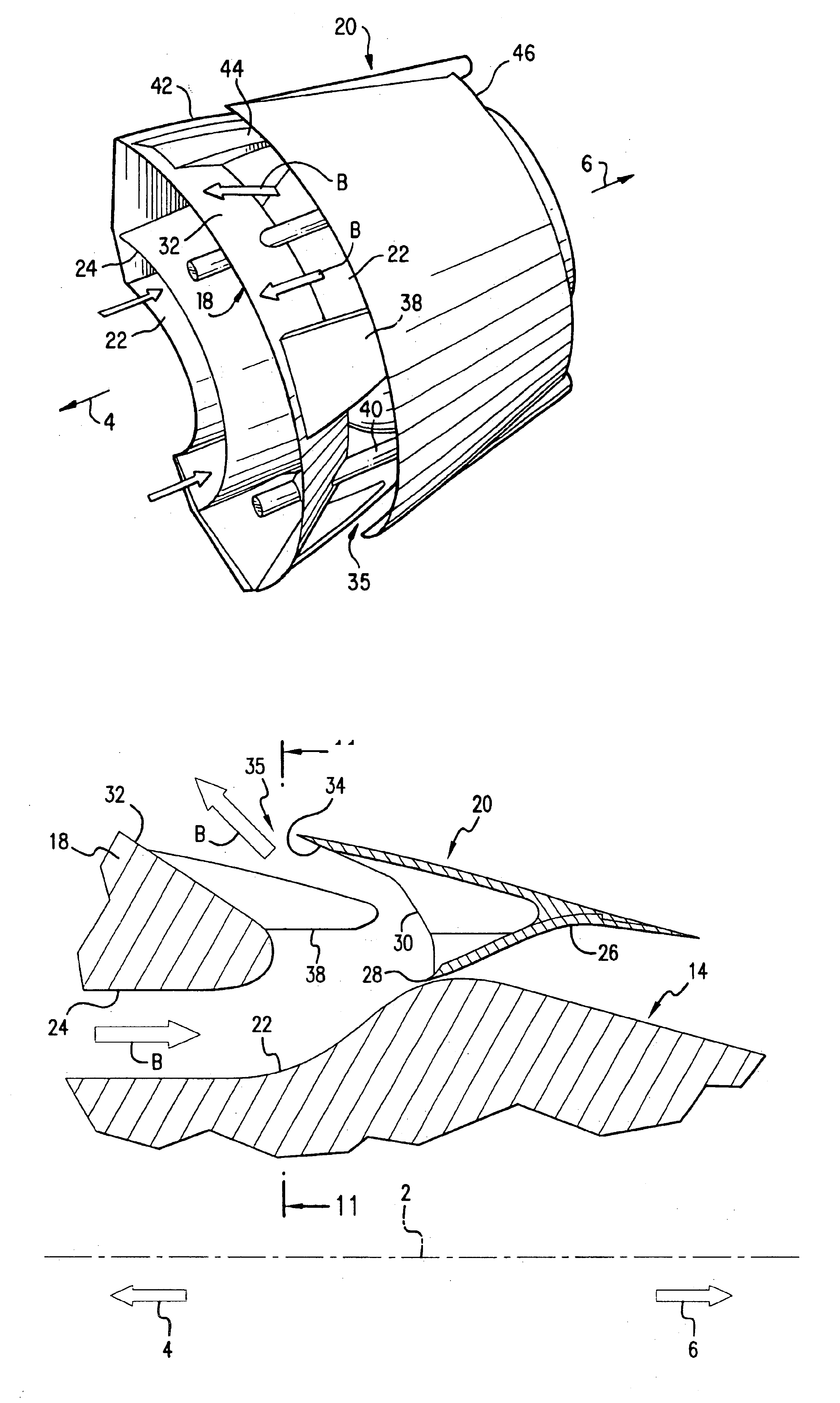
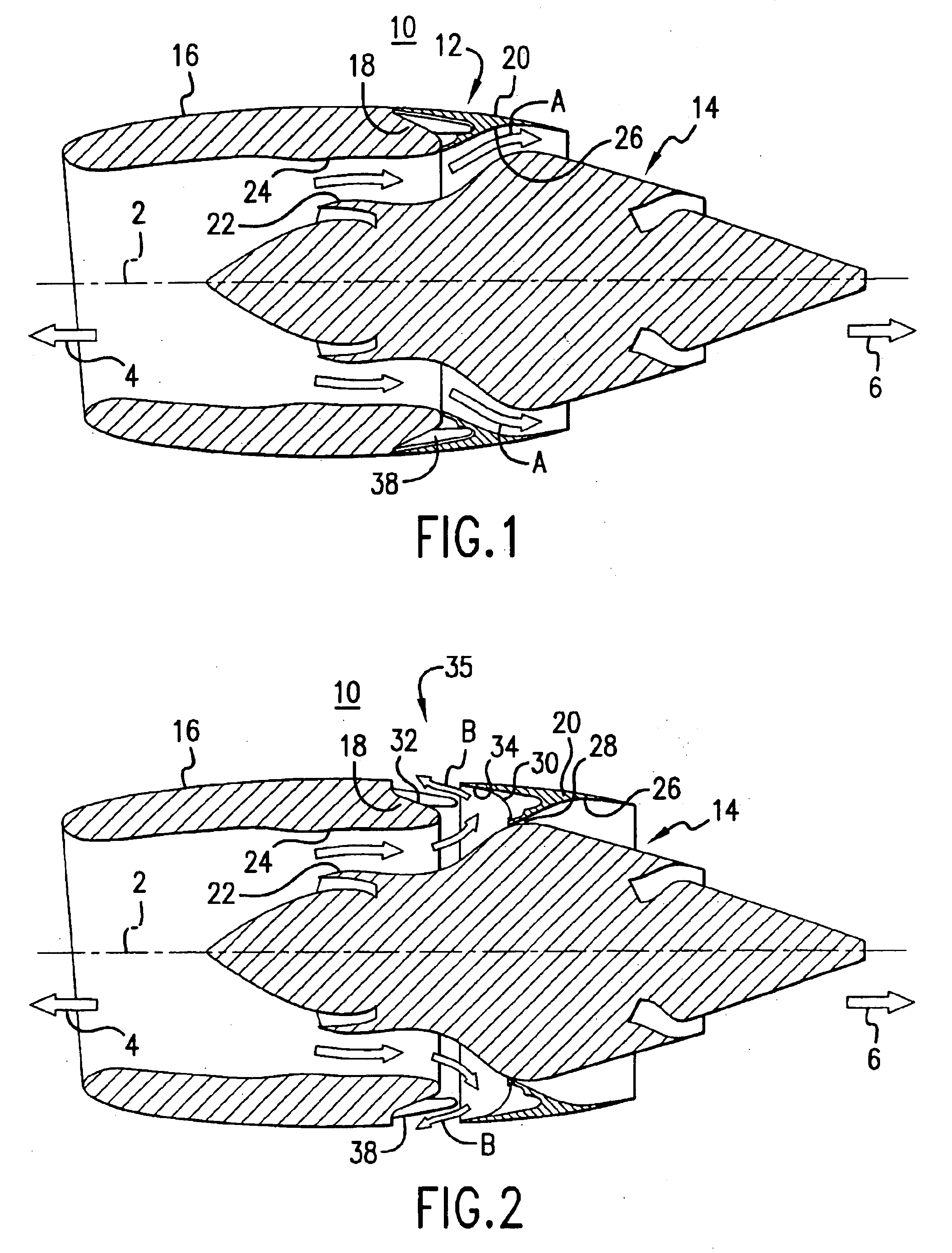
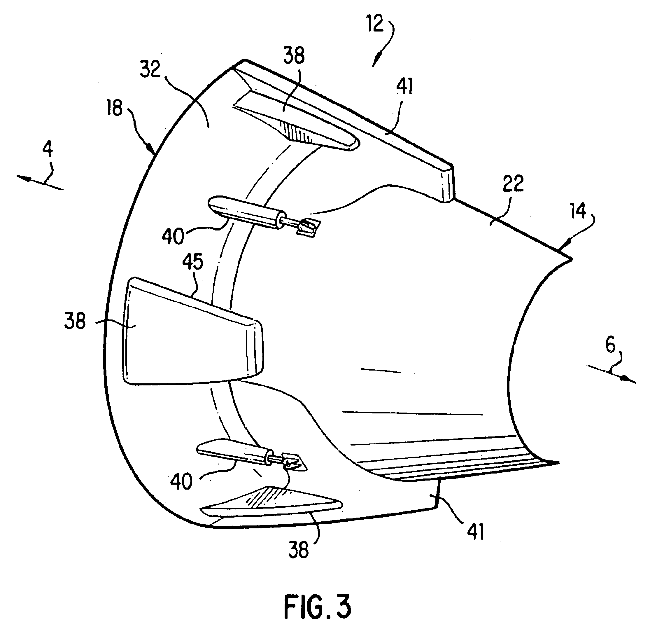
[0043]In accordance with the invention, an exemplary embodiment of a thrust reverser 12 used with a turbofan nacelle 10 is illustrated in FIGS. 1-2. In the description that follows, the center line of the nacelle 10 (also referred to herein as the longitudinal axis) is indicated by dotted line 2, the forward direction is indicated by arrow 4, and the aft direction is indicated by arrow 6. In the exemplary embodiment, an annular air duct is defined between the engine 14, and the fan cowl 16. The aft portion of the fan cowl 16 may include a torque box or bulkhead 18, which cooperates with a translating cowl 20. The translating cowl 20 is movable between a forward position and an aft position by a series of actuators (not shown). FIG. 1 illustrates the translating cowl 20 in a forward position, such that the translating cowl 20 and the bulkhead 18 are in contact or closely spaced with respect to one another, and having a conventional seal therebetween as is well known in the art, and t...


PUM


Abstract

A thrust reverser for a turbofan engine having an air duct defined radially inwardly by a wall around the turbofan engine and radially outwardly in part by a fan cowl of the engine. A bulkhead is adapted to be mounted on the fan cowl having a shaped surface defining an upstream wall. A translating cowl is supported for movement axially between a closed position substantially adjacent the bulkhead and an open position spaced axially apart from the bulkhead so as to form an outlet for discharge of air from the air duct. The translating cowl has a first wall and a kicker plate defining a shaped surface. The kicker plate and/or the bulkhead may have a dimension which varies at different radial locations about a circumference of the translating cowl to selectively control the forward component of velocity of the air discharged from the air duct. A plume control device may extend longitudinally across the outlet to divide the air discharged from the air duct into a plurality of plumes. A vane spaced axially aft from the bulkhead has an airfoil section to guide air to the outlet in order to control turning and area match when the translating cowl is in the deployed position.

Description

BACKGROUND OF THE INVENTION[0001]1. Field of the Invention[0002]This invention relates to gas turbine engine thrust reversers, and more particularly to cascadeless, translating cowl thrust reversers for ducted fan gas turbine engines, which redirect the air flow in the duct outwardly and forwardly when the thrust reverser is deployed.[0003]2. Background Information[0004]One general type of thrust reverser for use with the air duct of a turbofan engine incorporates a translating cowl that forms a rearward, outer wall portion of the air duct. For normal rearward air flow through the air duct, the translating cowl resides in a closed position in which its forward end engages a bulkhead that is mounted on the fan cowl of the engine. To reverse the air flow, the translating cowl is moved in an aft direction away from the bulkhead leaving an outlet opening aft of the bulkhead through which air is discharged from the air duct. The thrust reverser also provides for blocking of the air duct ...

Claims


Application Information

Patent Timeline
IPC IPC(8): F02K1/72
CPCF02K1/72
Inventor RAMLAOUI, JIHAD I.SEAVER, RANDALL J.JAMES, NORMAN J.BYRNE, STUART J.CORNEJO, SHEILA
Owner ROHR INC
Why Eureka
Try Eureka