Electronically controllable braking system and method for controlling the electronically controllable braking system

A technology of electronic control and braking system, which is applied in the direction of braking safety system, braking control system, braking action activation device, etc. It can solve the problems that the trailer control valve is not powered and can no longer be implemented.

Active Publication Date: 2019-11-12
WABCO GMBH
View PDF7 Cites 1 Cited by
  • Summary
  • Abstract
  • Description
  • Claims
  • Application Information

AI Technical Summary

Problems solved by technology

However, purely electronic brake presetting or possibly automatic presetting of auxiliary braking presetting as described in EP 2 090 481 B1 will no longer be possible, neither in the towing vehicle nor in the trailer
[0012] Furthermore, it is disadvantageous that, in the event of a failure of the first energy source, a redundant implementation of the purely electrically present brake presetting cannot be carried out directly via the trailer control valve, since in the event of such an electrical failure, the trailer control The valve will not be energized and therefore the trailer control valve can only be actuated pneumatically via the front axle brake circuit
In the event of an electrical failure, therefore, purely electric drive via a direct route via the trailer control valve is under no circumstances possible

Method used


Image

  • Electronically controllable braking system and method for controlling the electronically controllable braking system
  • Electronically controllable braking system and method for controlling the electronically controllable braking system
  • Electronically controllable braking system and method for controlling the electronically controllable braking system

Examples


Embodiment Construction

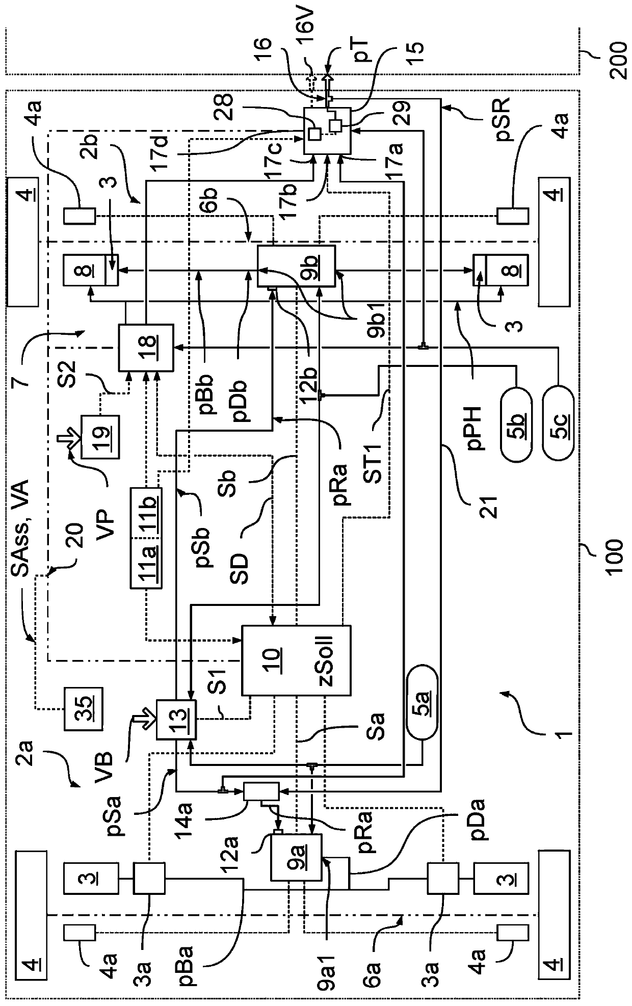
[0064] exist Figure 1a A vehicle 100 is shown schematically with a braking system 1 which can brake in two service brake circuits 2 a , 2 b via service brakes 3 on wheels 4 . The front axle service brake circuit 2a is assigned to the front axle 6a, and the rear axle service brake circuit 2b is assigned to the rear axle 6b. Further axles can also be provided, to which service brake circuits 6 a and 6 b or further service brake circuits are assigned. A pressure medium store 5 a , 5 b is assigned to the service brake circuits 2 a , 2 b per bridge.

[0065] A parking brake circuit 7 is also assigned to the rear axle 6b, wherein the wheels 4 on the rear axle 6b can be braked in the parking brake circuit 7 via a spring accumulator brake 8, so that the wheels of the rear axle 6b 4 Deceleration is possible not only in the rear axle service brake circuit 2 b via the service brake 3 , but also in the parking brake circuit 7 via the spring accumulator brake 8 . For this purpose, a com...


PUM


Abstract

The invention relates to an electronically controllable braking system (1), comprising a trailer control valve (15), which has a trailer control module (28), the trailer control module (28) being designed to receive and process an electronically transmitted braking specification (VA, VB, VP) and the trailer control valve (15) being designed, under the control of the trailer control module (28), toproduce and output a redundancy control pressure (pSR) in accordance with the electronically transmitted braking specification (VA, VB, VP). If an implementation of the braking specification (VA, VB,VP) by means of at least one service brake circuit (2a, 2b) by the control of a service-brake brake pressure (pBa, pBb), which implementation is electrically controlled by means of a service brake control module (10), is prevented, the service-brake brake pressure (pBa, pBb) can be produced in accordance with the redundancy control pressure (pSR) produced in the trailer control valve (15) and output to the service brakes (3) of the at least one service brake circuit (2a, 2b) for the redundant implementation of the brake specification (VA, VB, VP) in the vehicle (100) and/or a trailer controlpressure (pT) can be produced in accordance with the redundancy control pressure (pSR) produced in the trailer control valve (15) and can be output to a trailer (200) for the redundant implementationof the brake specification (VA, VB, VP) in the trailer (200).

Description

technical field [0001] The invention relates to an electronically controllable braking system and a method for controlling an electronically controllable braking system. Background technique [0002] The braking system in a vehicle, preferably a commercial vehicle, can be provided with two or more service brake circuits and a parking brake circuit, in which the service brakes that are regulated to the service brakes are adjusted Brake pressure, in the parking brake circuit, sets the parking brake pressure that is regulated to the spring-loaded brake. The brake pressure of the service brake is regulated to the service brake, for example, via a pressure modulator which is based on a service brake braking specification in the form of a pneumatic service brake control pressure or an electrical service brake control signal. output the service brake pressure to the respective service brake. [0003] In normal operation, the presetting to the pressure modulator takes place electr...

Claims


Application Information

Patent Timeline
Patent Type & Authority Applications(China)
IPC IPC(8): B60T13/66B60T13/68B60T17/22
CPCB60T7/02B60T7/04B60T7/042B60T7/12B60T13/66B60T13/662B60T13/68B60T13/683B60T13/74B60T17/22B60T8/17B60T15/027B60T2240/00B60T2270/403B60T2270/413
Inventor 朱利安·万蒂勒
Owner WABCO GMBH
Why Eureka
Try Eureka