Shift drum angle detecting device for transmission

a technology of shifting drum and detection device, which is applied in the direction of gearing control, mechanical equipment, instruments, etc., can solve the problems of unstable output voltage between the first angle sensor and the second angle sensor, and the inability to smoothly move the shift fork, so as to achieve the effect of high-precision detection of the rotational angle of the shift drum

Active Publication Date: 2021-04-01
HONDA MOTOR CO LTD
View PDF1 Cites 0 Cited by
  • Summary
  • Abstract
  • Description
  • Claims
  • Application Information

AI Technical Summary

Benefits of technology

[0029]In this configuration, in the state where the roller fits into the recessed part of the neutral position of the star-shaped cam, the first sensor switching angle is set to the rotational angle toward, out of the projecting parts on both sides and continuous to the recessed part, the projecting part having the narrower non-stable-rotation angle region on the side farther from the swing center of the detent arm. Thus, the first sensor switching angle is set to the farthest possible position from the center of the recessed part. This realizes highly precise detection of the rotational angle of the shift drum over a wider range around the center of the recessed part of the star-shaped cam where the shift stage is established, while minimizing the influence of the first sensor switching angle.

Problems solved by technology

That is, the shift forks cannot be smoothly moved.
At any shift drum angle, when both the first angle sensor and the second angle sensor output the voltage of 0, that is, when the voltage switching takes place simultaneously, the output voltage is unstable with both the first angle sensor and the second angle sensor.
Thus, the rotational angle of the shift drum cannot be precisely detected, which influences actuator control.

Method used


Image

  • Shift drum angle detecting device for transmission
  • Shift drum angle detecting device for transmission
  • Shift drum angle detecting device for transmission

Examples


Embodiment Construction

[0049]In the following, with reference to FIGS. 1 to 15, a description will be given of an embodiment of the present invention.

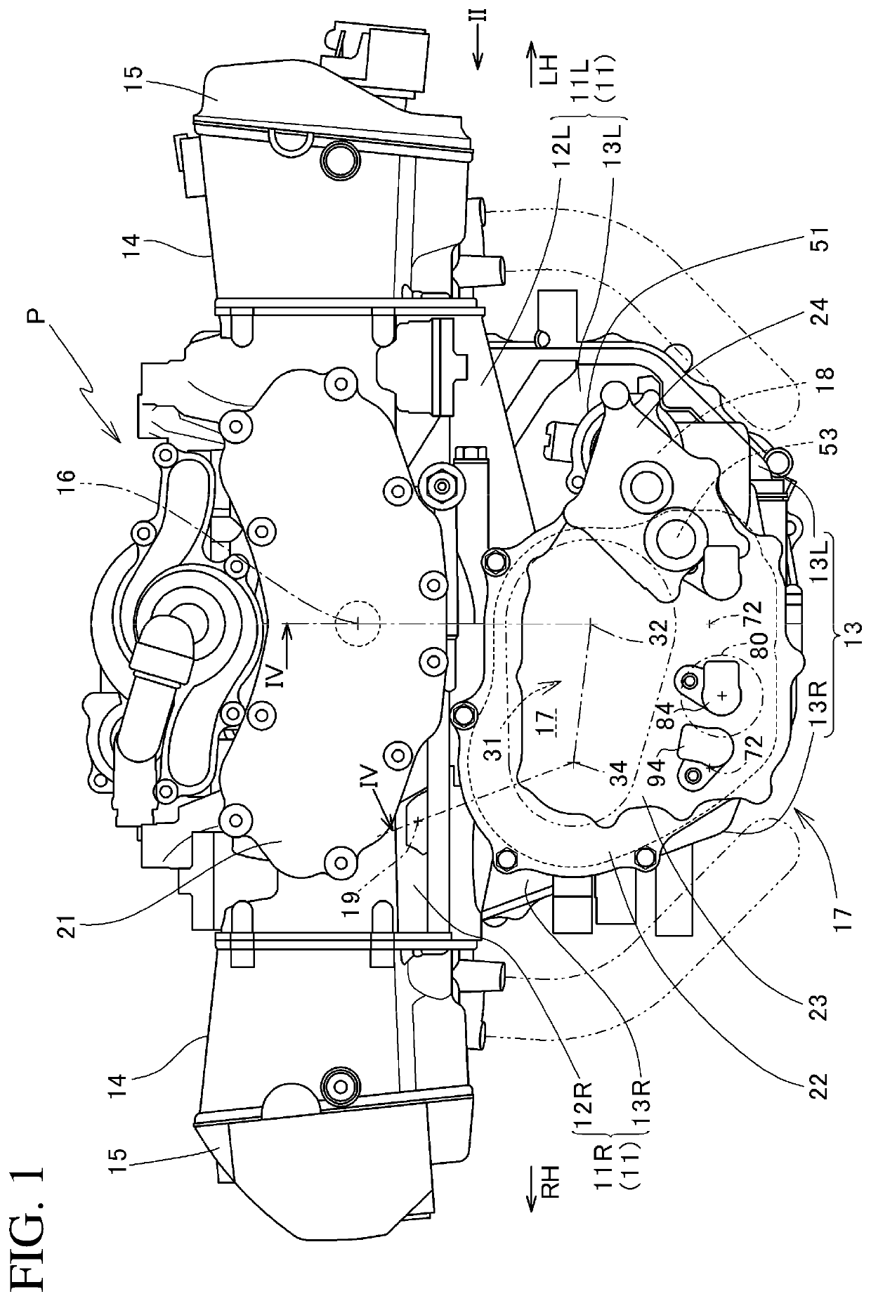
[0050]FIG. 1 is a partially omitted front view of a power unit P equipped with a shift drum angle detecting device for a transmission according to an embodiment of the present invention.

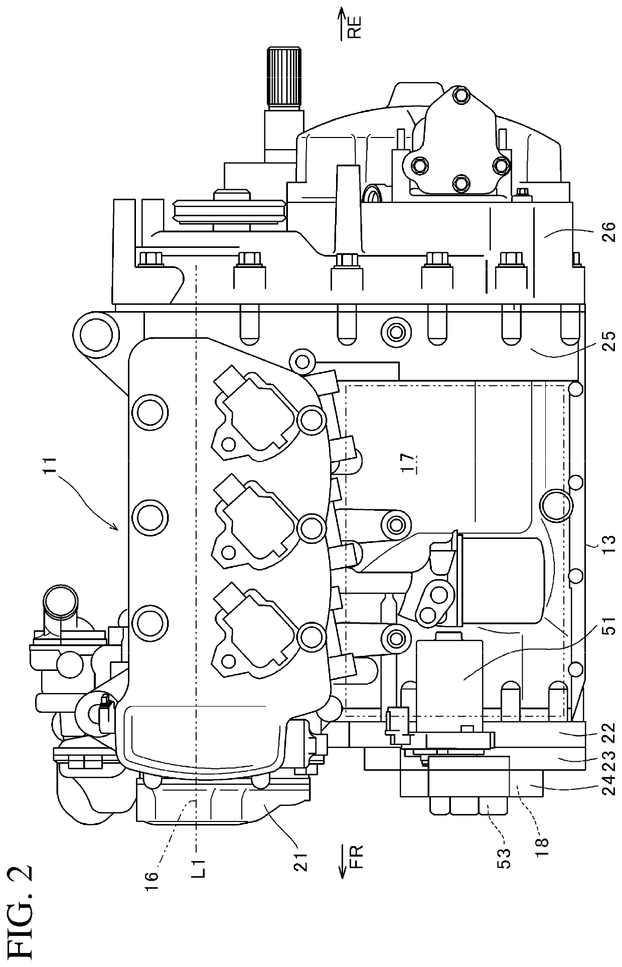
[0051]FIG. 2 is a left side view of a power unit P taken along line II in FIG. 1.

[0052]The power unit P includes: a flat-six water-cooled four-stroke engine E mounted on the motorcycle in a so-called longitudinal orientation having its crankshaft oriented in the vehicle front-rear direction; and a dual clutch transmission 31 coupled to the engine E so as to convert the power of the engine E to a predetermined shift stage.

[0053]In the description, the terms front, rear, right, and left are based on the ordinary standard in which the forward traveling direction of the motorcycle equipped with the power unit P is the front side. In the drawings, FR indicates the front side, RR i...


PUM


Abstract

A shift drum angle detecting device includes: a first angle sensor configured to output a first sensor output value corresponding to a shaft rotational angle of a first sensor shaft integrally rotating with a shift drum; and a second angle sensor configured to output a second sensor output value corresponding to a shaft rotational angle of a second sensor shaft rotating at an increased speed as a result of a speed increasing mechanism increasing the rotation of the first sensor shaft. A first sensor switching angle where the maximum value and the minimum value of the first sensor output value are switched and a second sensor switching angle where the maximum value and the minimum value of the second sensor output value are switched are set to be different from each other in rotational angle of the shift drum. Such device precisely detects any rotational angle of the shift drum.

Description

BACKGROUND1. Technical Field[0001]The present invention relates to a shift drum angle detecting device that precisely detects the rotational angle of a shift drum for a transmission of a vehicle.2. Description of the Background[0002]In a conventional dual clutch transmission for a vehicle, a shift drum in a change mechanism of the transmission rotates to move shift forks. The moved shift forks move shifter gears to switch the shift stage (see Patent Literature 1).[0003]For example, when a speed change is made from the first speed to the second speed, the gear position of the shift drum is switched from the first speed position (1-n) through the first speed-second speed preparatory position (1-2) to the second speed position (n-2).CITATION LISTPatent Literature[0004]Patent Literature 1: Japanese Patent No. 6226848[0005]The transmission disclosed in Patent Literature 1 has shift stages of seven speeds and the reverse position. Accordingly, fifteen gear positions are provided at the sh...

Claims


Application Information

Patent Timeline
Patent Type & Authority Applications(United States)
IPC IPC(8): G01B7/30F16H63/18
CPCG01B7/30F16H63/18F16H59/70G01D5/165
Inventor ADACHI, JUNKOJIMA, HIROYUKITOKITO, AKIRAFURUSAWA, YOSHIKAZU
Owner HONDA MOTOR CO LTD
Why Eureka
Try Eureka