Hollow Core Photonic Crystal Fibre Comprising a Fibre Grating in the Cladding and Its Applications

a photonic crystal fibre and core technology, applied in the field of hollow core photonic crystal fibre comprising a fibre grating in the cladding and its application, can solve the problems of light power loss of the order of 1 db per splice, device is therefore less useful for applications, and the achievable reflection remains limited in these assemblies, so as to achieve large reflectivity and high reflectivity. the effect of large finess

Inactive Publication Date: 2011-11-03
GLOPHOTONICS
View PDF6 Cites 24 Cited by
  • Summary
  • Abstract
  • Description
  • Claims
  • Application Information

AI Technical Summary

Benefits of technology

[0008]The invention is set out in the claims. Because a fibre includes an optical propagation core surrounded by cladding, wherein the cladding includes a reflection region of varying refractive index along a longitudinal section of the fibre, full 3-dimensional confinement is achieved within the fibre. There is no need to embed the fibre within portions of standard optical fibre or between any other devices in order to achieve this confinement. Hence a compact optical fibre cavity is provided. The absence of splices and the large reflectivity achievable as a result of the cladding refractive index modulation confers the cavity with large finesse. In particular, by defining the reflection region via formation of a Bragg Grating in the material of the cladding, the fibre can be arranged to act as an air mirror

Problems solved by technology

However, because these microcells rely on splicing standard optical fibre (solid core based on doped silica) to each end of a section of HC-PCF, light power losses—of the order of 1 dB per splice—are incurred.
However, due to the inevitable scattering which occurs at each fibre splice, the achievable reflection remains limited in these assemblies and the finesse of the forme

Method used


Image

  • Hollow Core Photonic Crystal Fibre Comprising a Fibre Grating in the Cladding and Its Applications
  • Hollow Core Photonic Crystal Fibre Comprising a Fibre Grating in the Cladding and Its Applications
  • Hollow Core Photonic Crystal Fibre Comprising a Fibre Grating in the Cladding and Its Applications

Examples


Embodiment Construction

[0050]Referring to the Figures, the invention can be seen in more detail.

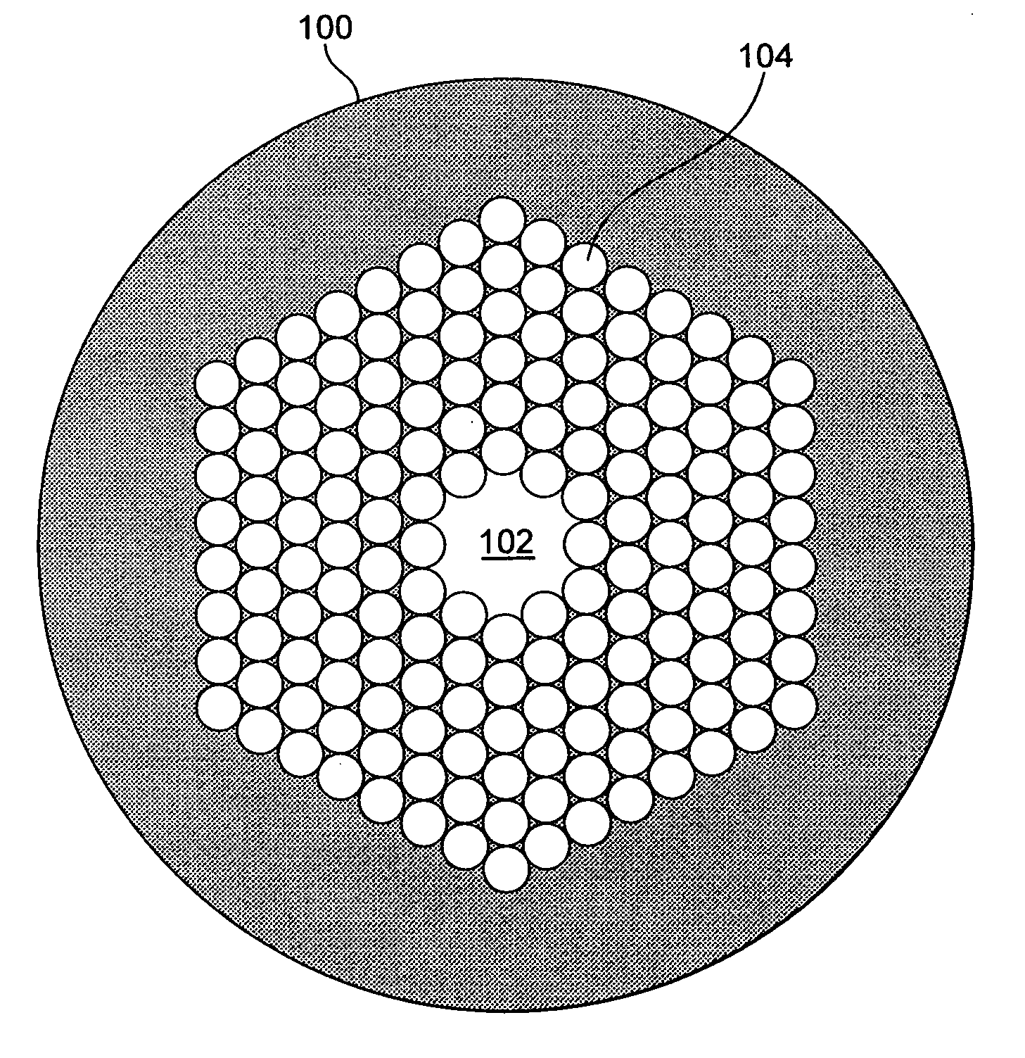
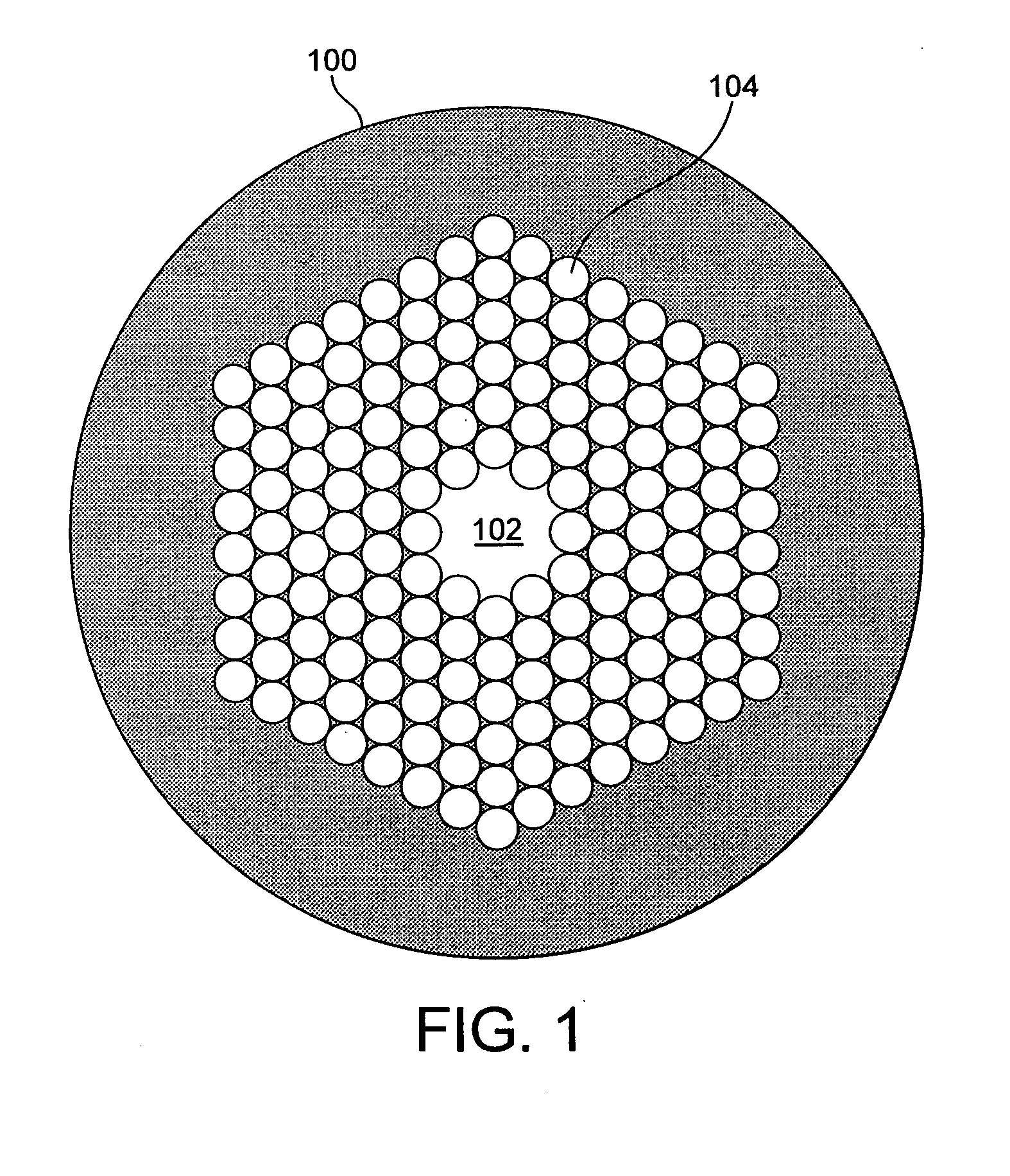
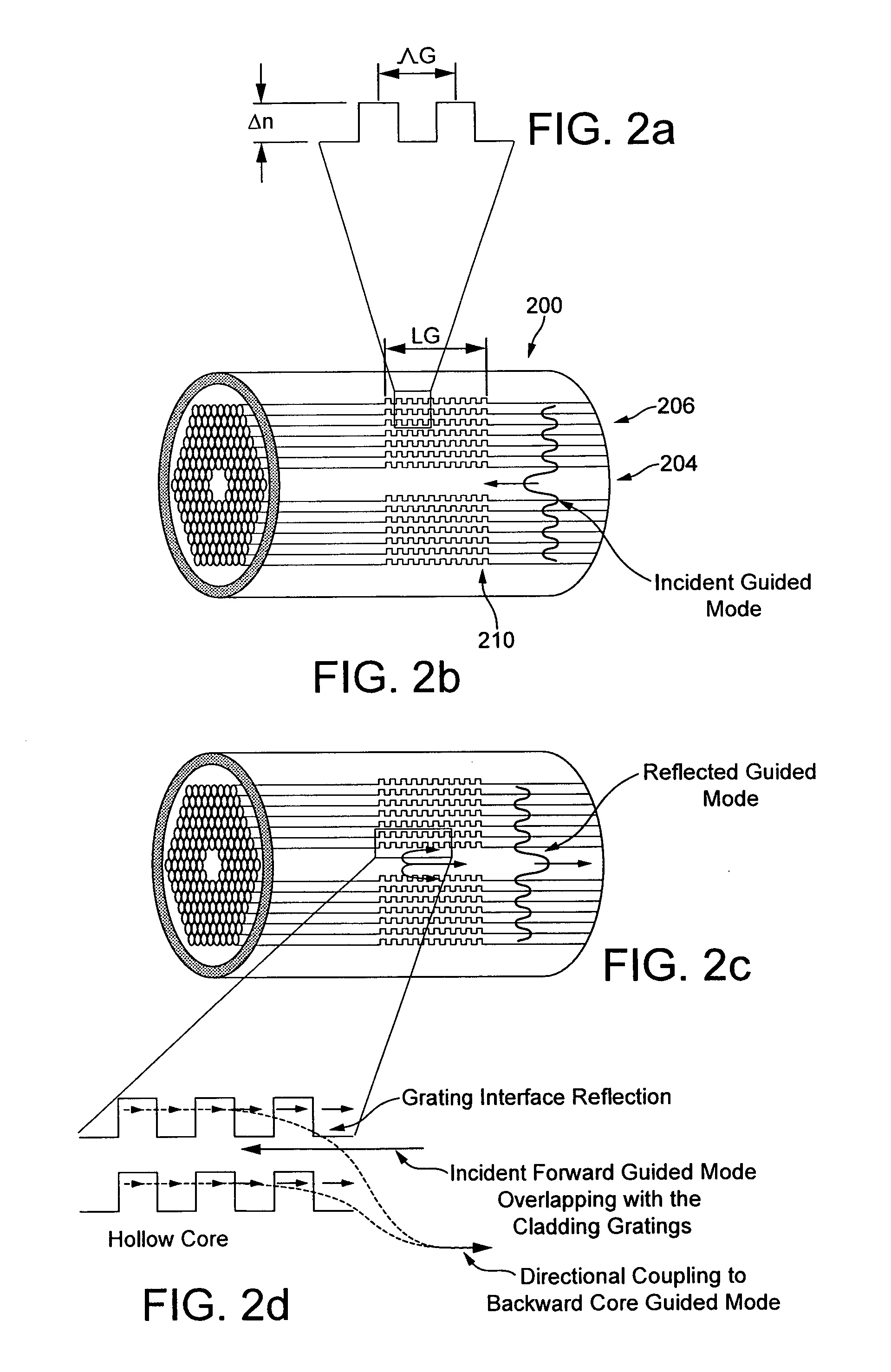
[0051]As shown, for example, in FIGS. 2b, 2c and 2e, an optical fibre 200 comprises a Hollow Core Photonic Crystal Fibre (HC-PCF) having a hollow core 204 surrounded by a cladding 206 of silica microcapillaries. A HC-PCF is the preferred waveguide for the optical fibre 200 since it allows unprecedented interaction between light and a gas contained within the core 204 of the fibre. However, it will be appreciated that any appropriate fibre or wave guide may be used. It will further be appreciated that light which is directed along the core 204 of the HC-PCF is confined in two dimensions, radially outward of the longitudinal axis of the core 204, due to the photonic band gap imposed by the holey fibre cross-section of the cladding 206. In the embodiments shown, a portion of the cladding 206 is then arranged to form a longitudinal cavity 208 within the core 204 of the fibre in order to form an “air mirror” and ach...


PUM


Abstract

An optical fibre is provided having a fibre cladding around a longitudinally extending optical propagation core. The cladding has a reflection region of a varying refractive index in the longitudinal direction.

Description

[0001]This invention relates to an optical fibre and method.BACKGROUND SECTION[0002]Hollow Core Photonic Crystal Fibres (HC-PCF), also known as a band-gap fibres, air-guiding band-gap fibres, or microstructured fibres, are well known in the industry and have been the object of an ever growing interest over the past decade. Known applications of HC-PCF span from telecoms and metrology to gas-laser systems, as described for example in “Stimulated Raman Scattering in Hydrogen-Filled Hollow-Core Photonic Crystal Fibre,” by F. Benabid, J. C. Knight, G. Antonopoulos, and P. S. J. Russell, Science 298, 399-402 (2002) (“Benabid et al”) or in “Hollow-core photonic bandgap fibre: new light guidance for new science and technology”, by F. Benabid, Philos. Trans. R. Soc. A-Math. Phys. Eng. Sci. 364 (2006) 3439-3462.[0003]The basic structure of a HC-PCF is shown in FIG. 1 and will be familiar to the skilled reader. The fibre 100 includes a hollow core 102 surrounded by a cladding 104 of silica mi...

Claims


Application Information

Patent Timeline
IPC IPC(8): G01J3/44G06F17/50G02B6/028
CPCG02B6/02328G02B6/021
Inventor ROBERTS, PETER JOHNBENABID, ABDEL FETAH
Owner GLOPHOTONICS
Why Eureka
Try Eureka