Optical image measurement device and optical image measurement method

a technology of optical image and measurement device, which is applied in the field of optical image measurement device and optical image measurement method, can solve the problems of ophthalmic field, inability to acquire clear oct image, and decreased intensity of fundus oculi reflection light of signal light, so as to achieve easy acquisition of clear oct imag

Active Publication Date: 2009-10-20
KK TOPCON
View PDF8 Cites 27 Cited by
  • Summary
  • Abstract
  • Description
  • Claims
  • Application Information

AI Technical Summary

Benefits of technology

[0013]The present invention was made to solve such problems, and an object of the present invention is to provide a technique by which it is possible to easily acquire a clear OCT image even if an eye has a site reducing the intensity of a signal light.
[0014]Another object of the present invention is to provide a technique by which it is possible to prevent a case where a measurement is performed in the insufficiently aligned condition.
[0019]According to the present invention, it is possible to obtain the intensity distribution of an interference light based on the result of detection of the interference light; determine a projection position of a signal light to an eye based on this intensity distribution; and form an image of the eye based on the result of detection of a new interference light based on a new signal light projected toward the determined projection position of the signal light and a new reference light having passed through a reference object. Therefore, even if an eye has a site reducing the intensity of a signal light, it is possible to determine a projection position of the signal light so as to avoid the site, whereby it is possible to easily acquire a clear OCT image.
[0020]Further, according to the present invention, it is possible to previously grasp what image will be acquired actually, by forming an image based on an interference light acquired in a measurement for determining a projection position of a signal light. Therefore, it is possible to prevent a case where a measurement is performed in the insufficiently aligned condition.
[0021]Furthermore, according to the present invention, it is possible to obtain the intensity distribution of a reflected light based on the result of detection of the reflected light of a light projected to an eye; determine a projection position of a signal light to the eye based on this intensity distribution; and form an image of the eye based on the result of detection of an interference light generated by projecting the signal light to this projection position. Therefore, even if an eye has a site reducing the intensity of a signal light, it is possible to determine a projection position of the signal light so as to avoid the site, whereby it is possible to easily acquire a clear OCT image.

Problems solved by technology

Application of a conventional optical image measurement device in the ophthalmic field may cause problems as described below.
Therefore, the intensity of a fundus oculi reflection light of the signal light is decreased, and an interference light with sufficient intensity cannot be detected, with the result that a clear OCT image cannot be acquired.
Moreover, the accuracy of an OCT image may decrease resulting from scatter of the signal light at this site.
However, since such a preparation work requires a lot of effort, a load on the examiner increases.
Moreover, since the examination takes more time, a load on the patient also increases.
Especially in the case of performing plural times of measurement at a single site as in an observation of clinical course, it is necessary to perform alignment for every measurement, which is troublesome.
Further, in a conventional optical image measurement device, it is impossible to previously grasp what image will be acquired actually.
Therefore, there is a case where measurement is performed in the insufficiently aligned condition and an image is acquired at a site displaced from an observation target such as an optic disk, a macula and a lesion.
Consequently, it takes meaningless time and effort for measurement once more.

Method used


Image

  • Optical image measurement device and optical image measurement method
  • Optical image measurement device and optical image measurement method
  • Optical image measurement device and optical image measurement method

Examples


Embodiment Construction

[0031]An example of a preferred embodiment of the optical image measurement device and the optical image measurement method according to the present invention will be described in detail referring to the drawings.

[0032]The present invention is applied to use in the ophthalmic field. The present invention makes it possible to easily acquire a clear OCT image by determining the projection position of a light beam (a signal light) suited to an eye before actually acquiring the image.

[Device Configuration]

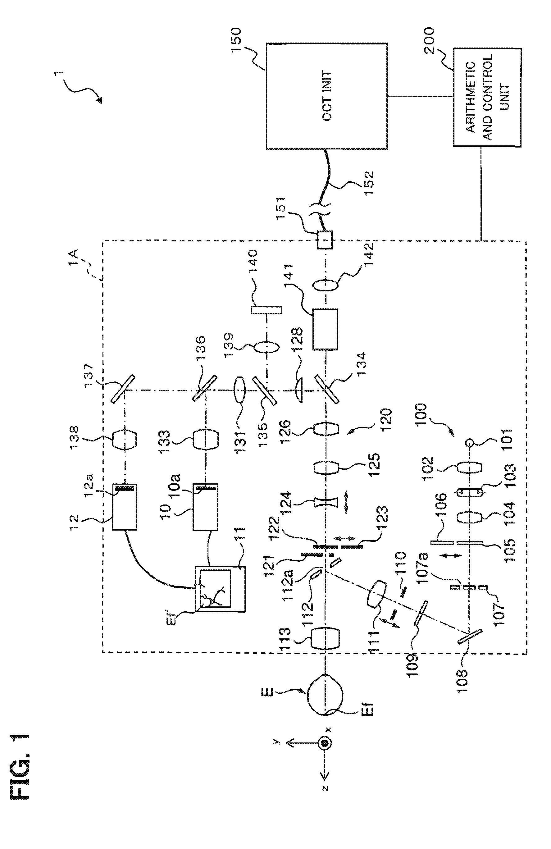
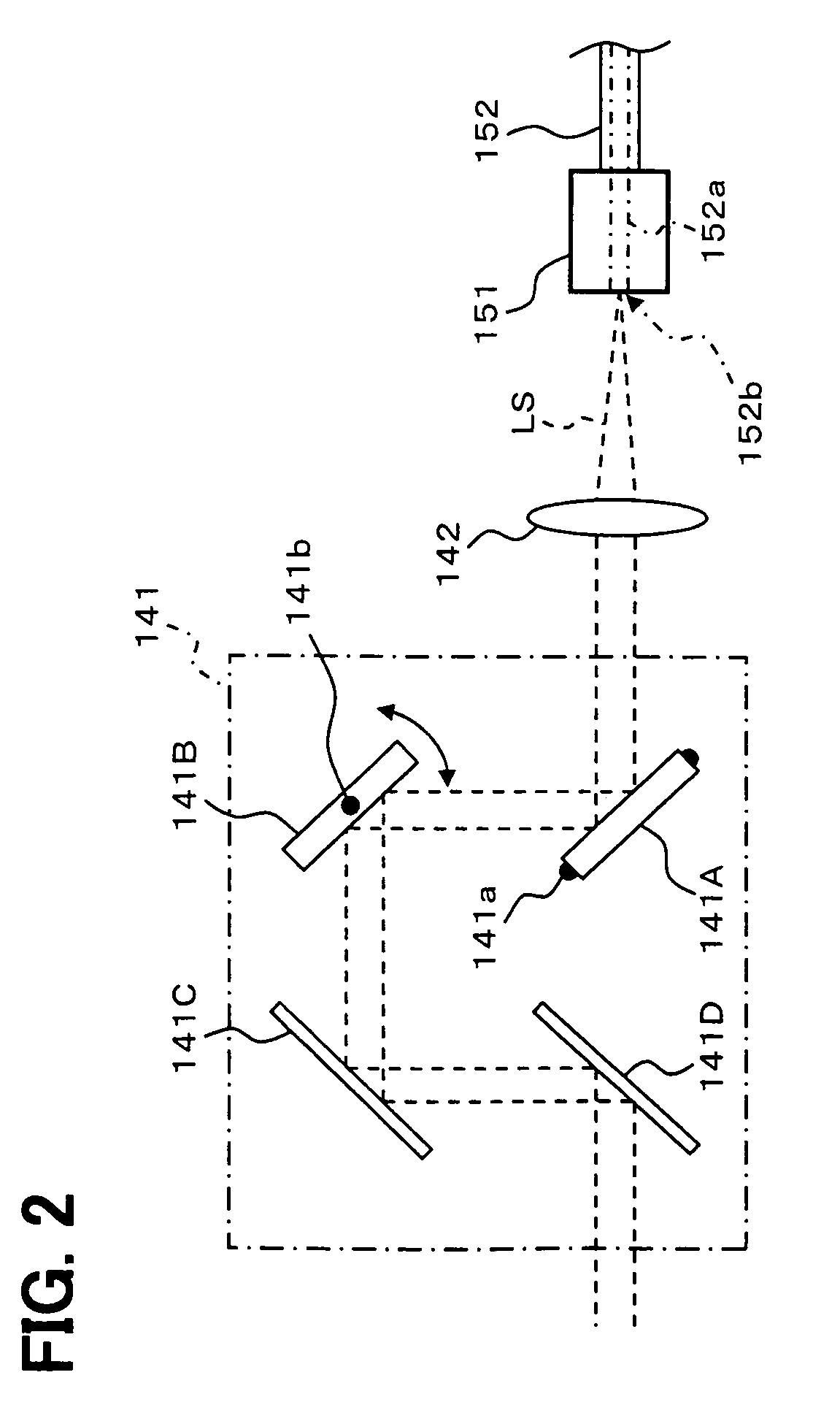
[0033]First, referring to FIGS. 1 to 6, the configuration in an embodiment of the optical image measurement device according to the present invention will be described. FIG. 1 shows an example of the entire configuration of a fundus oculi observation device 1 having a function as the optical image measurement device according to the present invention. FIG. 2 shows an example of the configuration of a scan unit 141 in a retinal camera unit 1A. FIG. 3 shows an example of the configuratio...


PUM


Abstract

An optical image measurement device comprises: an interference-light generator configured to generate an interference light by splitting a low-coherence light into a signal light and a reference light and superimposing the signal light having passed through an eye and the reference light having passed through a reference object; a detector configured to detect the generated interference light; a calculator configured to obtain intensity distribution of the interference light in the eye, based on a result of the detection by the detector; a determining part configured to determine a projection position of the signal light to the eye, based on the obtained intensity distribution; and an image forming part configured to form an image of the eye, based on a result of detection of a new interference light based on a new signal light projected toward the determined projection position and a new reference light having passed through the reference object.

Description

BACKGROUND OF THE INVENTION[0001]1. Field of the Invention[0002]The present invention relates to an optical image measurement device and an optical image measurement method for forming an image of an eye by projecting a light beam to the eye and using a reflected light therefrom.[0003]2. Description of the Related Art[0004]In recent years, attention has been focused on an optical image measurement technique of forming an image showing the surface morphology or internal morphology of a measurement object by using a light beam from a laser light source or the like. Because this optical image measurement technique does not have invasiveness to human bodies unlike an X-ray CT device, it is expected to employ this technique particularly in the medical field.[0005]Japanese Unexamined Patent Application Publication JP-A 11-325849 discloses an optical image measurement device configured in a manner that: a measuring arm scans an object by using a rotary deflection mirror (Galvano mirror); a...

Claims


Application Information

Patent Timeline
Patent Type & Authority Patents(United States)
IPC IPC(8): A61B3/14
CPCA61B3/102G01N21/4795G01B9/0203G01B9/02091G01B9/02067G01B9/02044G01B2290/65
Inventor FUKUMA, YASUFUMITSUKADA, HISASHIKIKAWA, TSUTOMUYUMIKAKE, KAZUHIKO
Owner KK TOPCON
Why Eureka
Try Eureka