Optical component and timepiece

a technology applied in the field of optical components and timepieces, can solve the problems of timepiece damage, reduced visibility, and inability to effectively prevent the adhesion of dirt due to static electricity or the like, and achieve excellent antistatic function, excellent antireflection function, and excellent antistatic function

Active Publication Date: 2016-06-09
SEIKO EPSON CORP
View PDF4 Cites 0 Cited by
  • Summary
  • Abstract
  • Description
  • Claims
  • Application Information

AI Technical Summary

Benefits of technology

[0028]Further, in the optical component according to the aspect of the invention, also an excellent antireflection function is exhibited, and therefore, the visibility of the time-displaying members such as a dial plate and hands disposed on the rear surface side of the cover glass can be made particularly excellent.
[0029]A timepiece according to an aspect of the invention includes the optical component according to the aspect of the invention.
[0030]According to this configuration, a timepiece including the optical component having an excellent antistatic function while having sufficient light transmittance can be provided.
[0031]According to the aspects of the invention, an optical component having an excellent antistatic function while having sufficient light transmittance can be provided, and also a timepiece including the optical component having an excellent antistatic function while having sufficient light transmittance can be provided.

Problems solved by technology

However, in the related art, adhesion of dirt due to static electricity or the like cannot be effectively prevented while ensuring the light transmittance of the optical component.
Therefore, the cover glass is a member in which a problem of decreasing the visibility particularly remarkably occurs when dirt such as dust adheres to the cover glass due to static electricity.
Further, in the case where the cover glass is undesirably charged with electricity, due to the effect, the hands such as an hour hand may be deformed, and therefore, a breakdown or the like of the timepiece may be caused due to such deformation.

Method used


Image

  • Optical component and timepiece
  • Optical component and timepiece
  • Optical component and timepiece

Examples


first embodiment

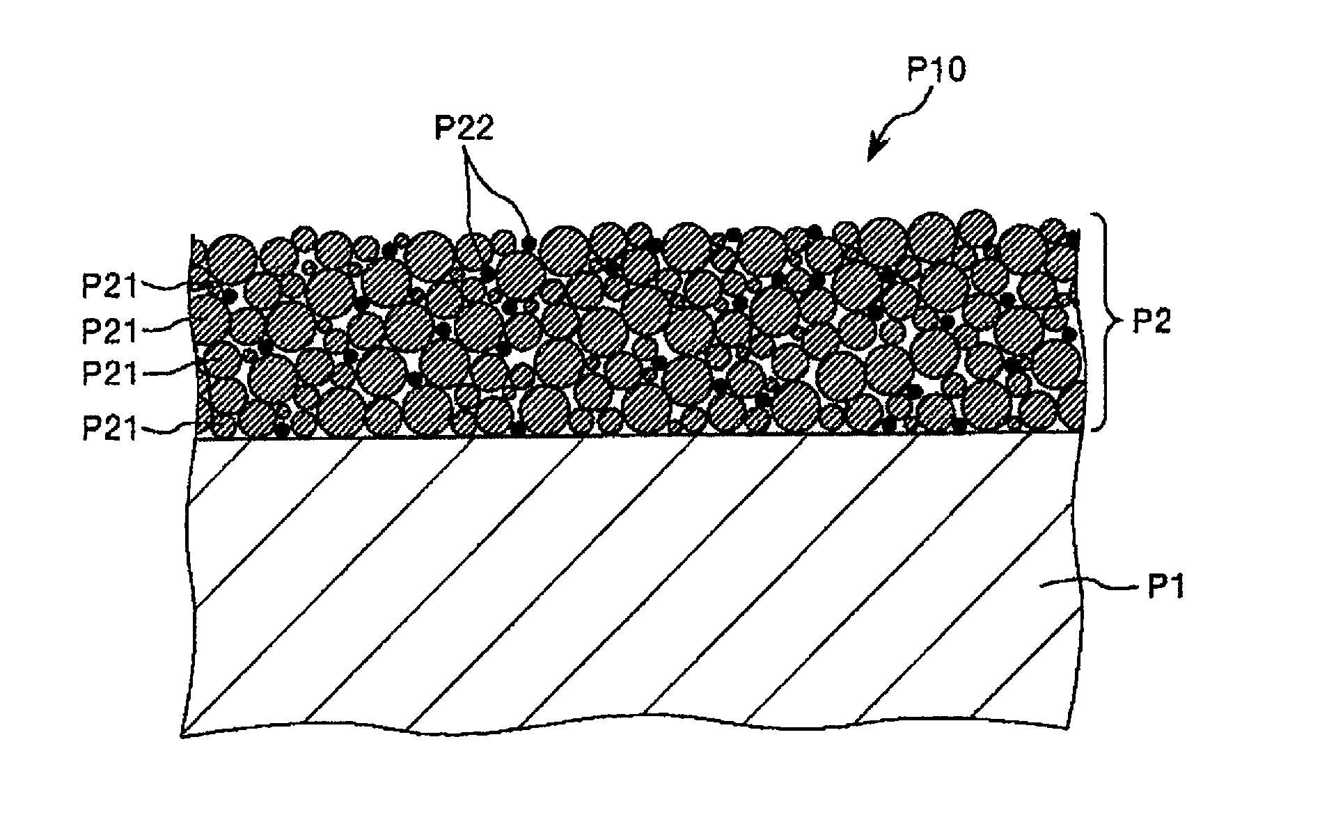
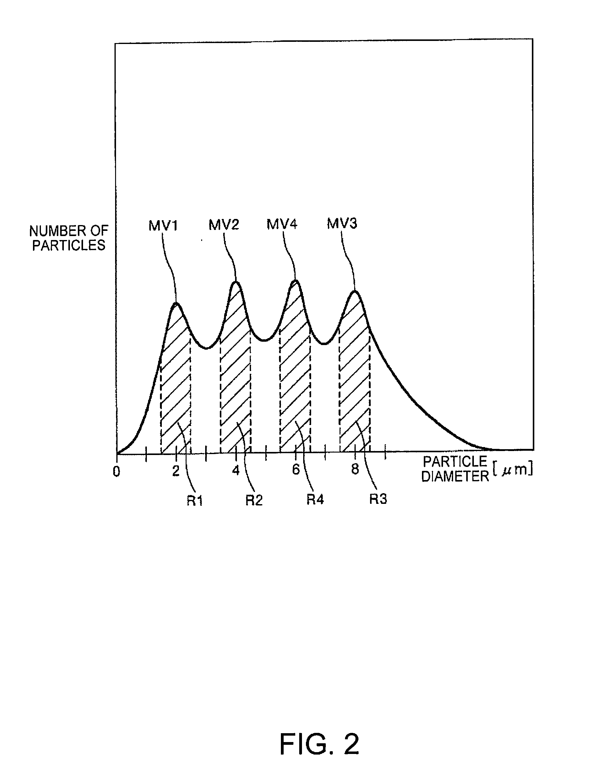
[0039]FIG. 1 is a cross-sectional view schematically showing a first embodiment of an optical component according to the invention, and FIG. 2 is a view schematically showing one example of a particle size distribution of silica particles constituting a film of an optical component according to the invention.

[0040]As shown in FIG. 1, an optical component P10 of this embodiment includes a base material P1 and a film P2 containing silica particles P21 and conductive transparent metal oxide particles P22.

[0041]According to such a configuration, the optical component P10 exhibits an antistatic function as a whole. In other words, the film P2 can function as an antistatic film. As a result, for example, the adhesion of dirt such as dust due to static electricity can be prevented, and thus, the optical component P10 can stably exhibit the inherent optical property.

[0042]The silica particles P21 and the conductive transparent metal oxide particles P22 are both a material with transparency,...

second embodiment

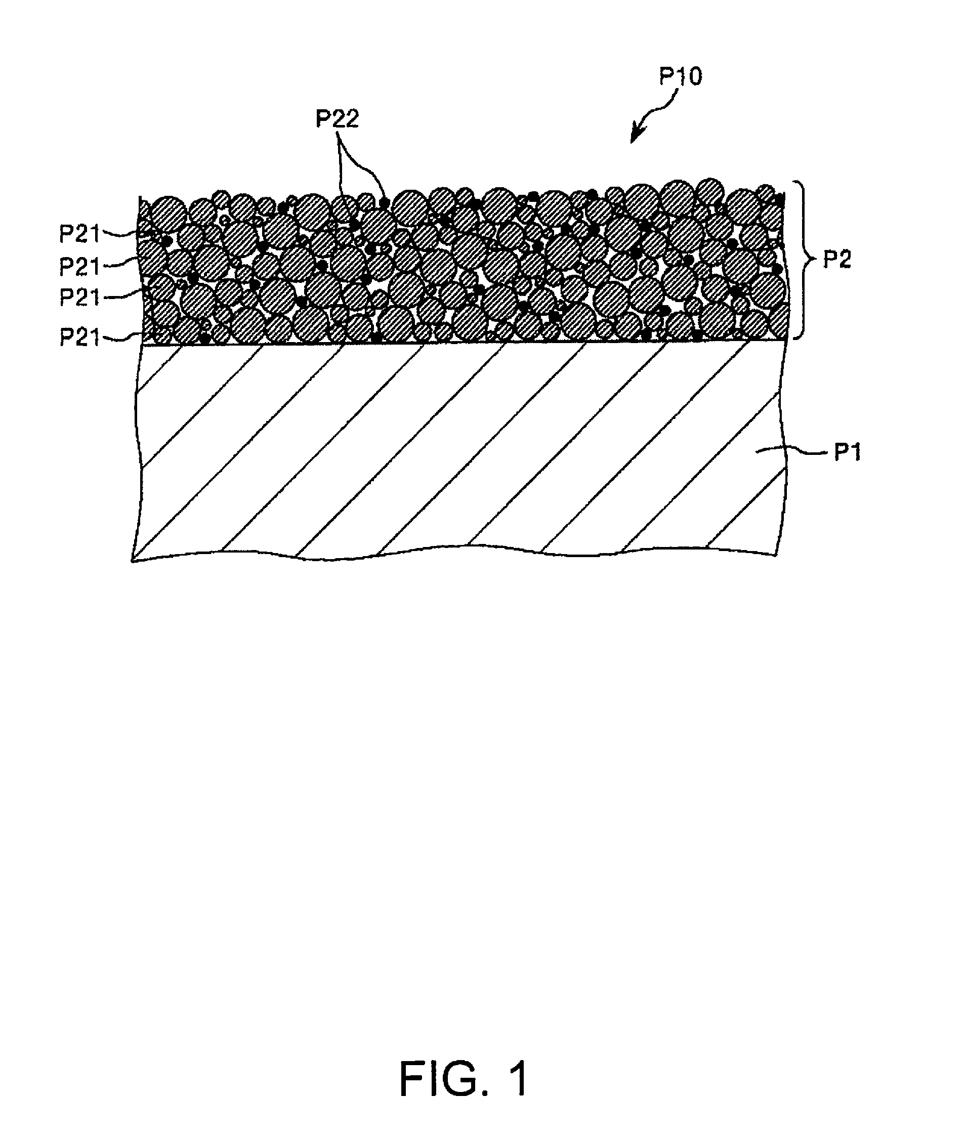
[0120]FIG. 3 is a cross-sectional view schematically showing a second embodiment of the optical component according to the invention. In the following description, different points from the above embodiment will be mainly described, and the description of the same matter will be omitted.

[0121]As shown in FIG. 3, an optical component P10 of this embodiment includes a base material P1, a film P2 containing silica particles P21 and conductive transparent metal oxide particles P22, and a foundation layer P3.

[0122]In this manner, by including the foundation layer P3, for example, the adhesiveness between the base material P1 and the film P2 (the adhesiveness through the foundation layer P3) can be made particularly excellent, and thus, the durability and reliability of the optical component P10 can be made particularly excellent.

[0123]Examples of a constituent material of the foundation layer P3 include various resin materials and SiO2.

[0124]The thickness of the foundation layer P3 is no...

example 1

[0192]By the method as described below, a cover glass as an optical component was produced.

[0193]First, a plate material (glass plate) composed of a sapphire glass was prepared as a base material (the base material preparation step), and a necessary part was cut and polished. The base material obtained by cutting and polishing had a substantially disk shape and had a size of 30 mm in diameter and 1 mm in thickness.

[0194]Subsequently, a UV irradiation treatment in which an ultraviolet ray with a wavelength of 248 nm was irradiated on the surface of the base material on the side where a film was going to be formed.

[0195]Subsequently, a film forming composition was applied onto the entire surface of one side of the base material by a spray coating method (film forming composition application step).

[0196]As the film forming composition, a composition obtained by mixing silica particles, tin oxide (SnO2) particles (number-based average particle diameter: 2.0 nm) as conductive transparent...


PUM

PropertyMeasurementUnit
volume resistivityaaaaaaaaaa
number-based average particle diameteraaaaaaaaaa

Abstract

An optical component includes a base material and a film containing silica particles and conductive transparent metal oxide particles. The conductive transparent metal oxide particles are preferably composed of SnO2. The number-based average particle diameter of the conductive transparent metal oxide particles is preferably 0.8 nm or more and 5.0 nm or less. When the content of the silica particles in the film is represented by Xs (vol %) and the content of the conductive transparent metal oxide particles in the film is represented by Xc (vol %), it is preferred to satisfy the following relationship: 0.003≦Xc/Xs≦0.12.

Description

BACKGROUND[0001]1. Technical Field[0002]The present invention relates to an optical component and a timepiece.[0003]2. Related Art[0004]In an optical component such as a cover glass for a timepiece, a material having high transparency such as any of various glass materials and various plastic materials is generally used.[0005]On such an optical component, for example, a film such as an antireflection film for the purpose of preventing undesirable light reflection is sometimes provided (see, for example, JP-A-2010-37115).[0006]However, in the related art, adhesion of dirt due to static electricity or the like cannot be effectively prevented while ensuring the light transmittance of the optical component.SUMMARY[0007]An advantage of some aspects of the invention is to provide an optical component having an excellent antistatic function while having sufficient light transmittance, and also to provide a timepiece including an optical component having an excellent antistatic function whi...

Claims


Application Information

Patent Timeline
Patent Type & Authority Applications(United States)
IPC IPC(8): G04B39/00G02B1/11G02B1/16
CPCG04B39/002G04B39/006G02B1/11G02B1/16G02B1/113
Inventor FURUSATO, DAIKISUZUKI, KATSUMI
Owner SEIKO EPSON CORP
Why Eureka
Try Eureka