Medical equipment management apparatus which predicts future status of medical equipment

a technology of medical equipment and management apparatus, applied in the field of medical equipment, can solve the problems of increasing annoyance and anxiety, reducing the throughput of imaging examination, and annoying specimens,

Inactive Publication Date: 2013-07-16
TOSHIBA MEDICAL SYST CORP
View PDF14 Cites 8 Cited by
  • Summary
  • Abstract
  • Description
  • Claims
  • Application Information

AI Technical Summary

Benefits of technology

[0011]According to a first aspect of the present invention, there is provided a medical equipment management apparatus for managing a medical equipment provided in a medical facility connected to the apparatus through a network. The apparatus includes a reception unit, a storage unit, a prediction unit, a determination unit, and an informing unit. The reception unit is configured to receive a parameter data regarding the medical equipment more than once, and the storage unit is configured to store the parameter data. The prediction unit is configured to calculate an expectancy of the parameter data to be received in the future based on the stored parameter data. Further, the determination unit is configured to determine a level of the expectancy, and the informing unit is configured to give a notice to the medical facility through the network according to the determined level.

Problems solved by technology

When, however, one apparatus operates during a period when it is difficult to maintain its normal performance during use of the apparatus for the specimen (such use may hereinafter be referred to as an imaging), it results in requiring another imaging for the same specimen.
This lowers a throughput of imaging examinations and annoys specimens, from a point of view of a medical facility where the one apparatus is provided.
Also from a specimen's point of view, it causes unnecessary X-ray exposure and restraint due to another imaging, and increase of annoyance and anxiety.
Although a maintenance service may be implemented according to the comparison with a predetermined reference value, it was not easy, for a hospital staff, a service center, and / or manufacturers of medical diagnosis apparatuses as well as maintenance personnel in the local maintenance provider, to comprehend a current status or situation of the medical diagnosis apparatus.
In other words, there was no way of easily and voluntarily knowing when a maintenance service is required; whether maintenance needs may arise earlier due to some reasons other than expected on the basis of experiences or may not arise for the time being; and so on.
In addition, the hospital staff could not easily know that a maintenance service was requested to the local maintenance provider, and details of the request (i.e., when the maintenance service will take place).
Therefore, the hospital staff could not have enough time, in some cases, to review and cope with in advance an effect on operations of the medical diagnosis apparatus due to the maintenance service.
On the other hand, for the maintenance personnel, there was not enough time in some cases to arrange a maintenance schedule and to order parts which may be needed in the maintenance service.

Method used


Image

  • Medical equipment management apparatus which predicts future status of medical equipment
  • Medical equipment management apparatus which predicts future status of medical equipment
  • Medical equipment management apparatus which predicts future status of medical equipment

Examples


first embodiment

(First Embodiment)

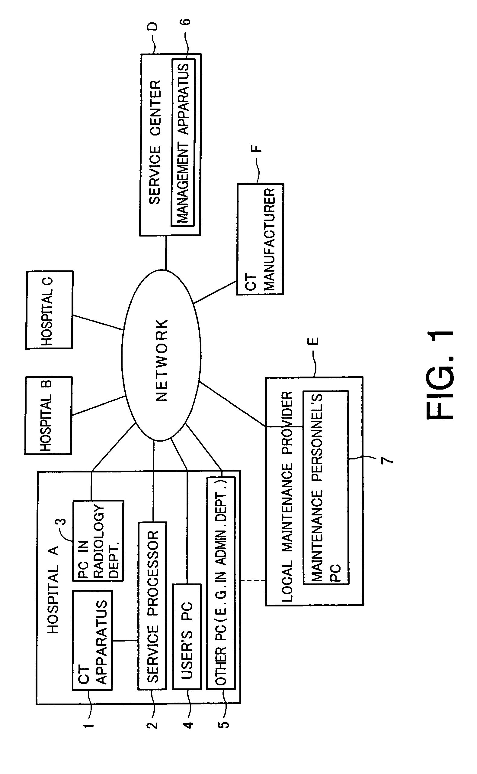
[0049]FIG. 1 is an illustration showing an exemplary overview of a medical system including a medical equipment management apparatus according to a first embodiment of the present invention. As shown in FIG. 1, hospitals A, B, and C are connected to a service center D through a network. Each of the hospitals A, B, and C includes one or more medical equipments such as the medical diagnosis apparatuses as described in the background of the invention. The service center D monitors the medical equipments provided in the hospitals A, B, and C. Further, a local maintenance provider E is connected to the network. The local maintenance provider E is provided in an area where the hospital A is located. If necessary, a CT manufacturer F may also be connected to the network.

[0050]In hospital A, a CT apparatus 1 is provided as the medical equipment. Although only the CT apparatus 1 will be described herein as an example of the equipment, the medical equipment provided in the h...

second embodiment

(Second Embodiment)

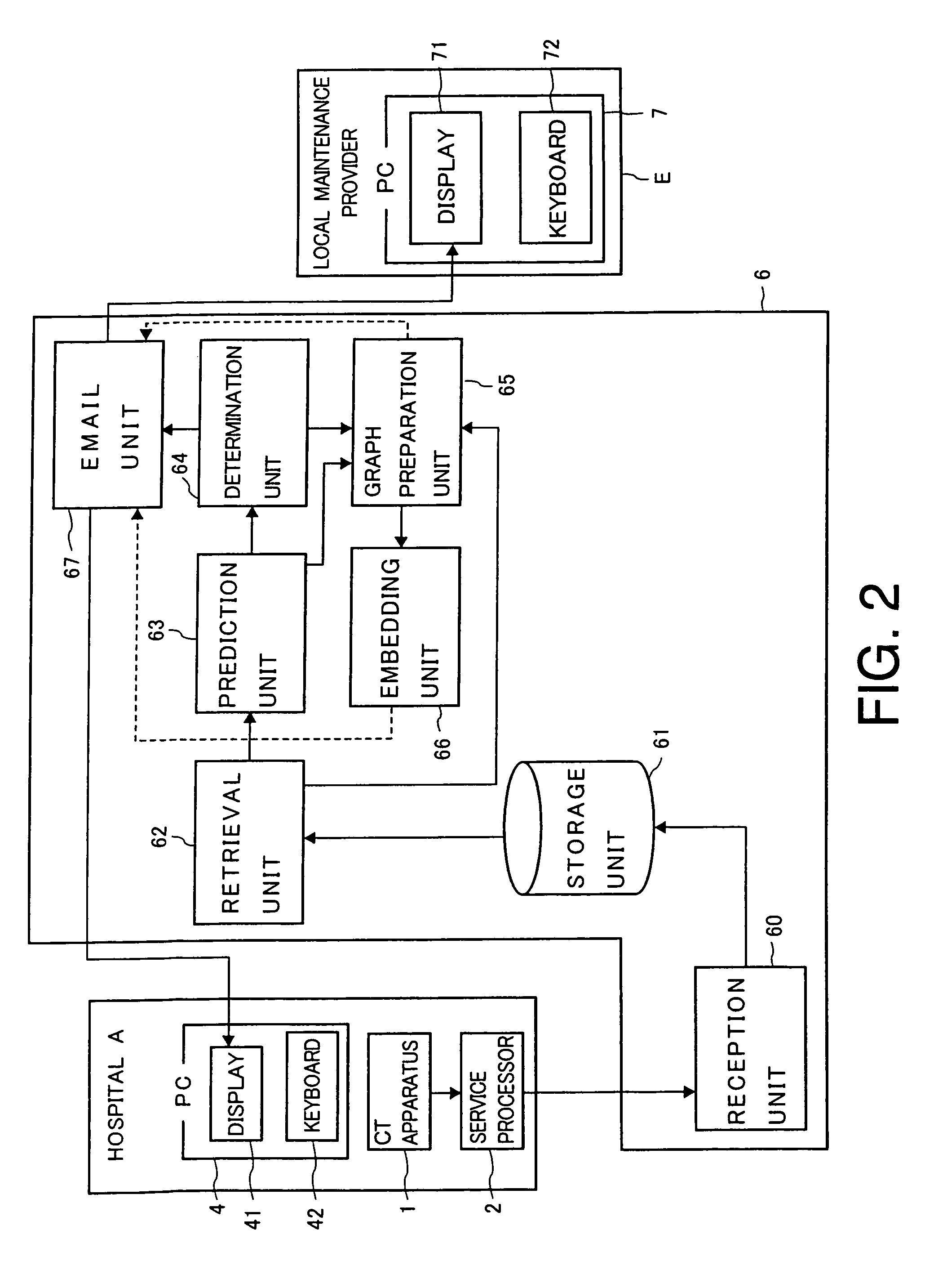
[0085]Another relationship among the hospital A, the medical equipment management apparatus 6, and the local maintenance provider E will be described with reference to FIG. 3. FIG. 3 is a block diagram showing a second exemplary configuration of the medical equipment management apparatus 6 in relationship to the hospital A and the local maintenance provider E according to a second embodiment of the present invention.

[0086]In FIG. 3, components, which operate in a manner similar to the components shown in FIG. 2 are given the same reference numbers and are detailed explanations of their components are appropriately omitted. In addition, operations of the medical equipment management apparatus 6 are similar to those described in the first embodiment except for those described below. Therefore, detailed explanations of such operations similar to those in the first embodiment are omitted.

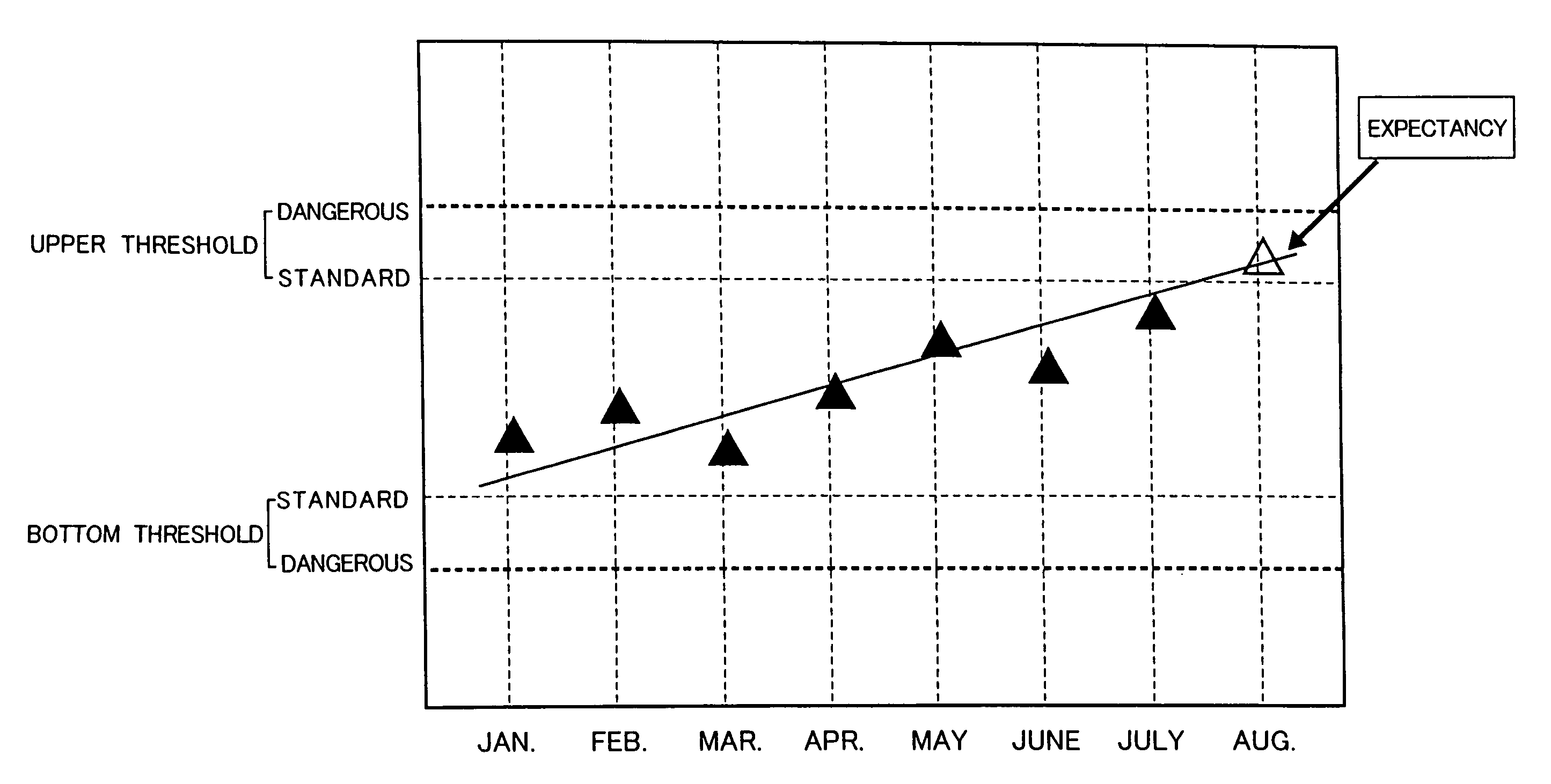
[0087]The medical equipment management apparatus 6 further includes an expectancy...

third embodiment

(Third Embodiment)

[0095]Requests from the hospital A has been described in the second embodiment of the present invention. Such requests may also be made from the local maintenance provider E.

[0096]FIG. 4 is a block diagram showing a third exemplary configuration of the medical equipment management apparatus 6 in relationship to the hospital A and the local maintenance provider E according to a third embodiment of the present invention.

[0097]In FIG. 4, components, which operate in a manner similar to the components shown in FIG. 2 or 3 are given the same reference numbers and detailed explanations are appropriately omitted. In addition, operations of the medical equipment management apparatus 6 are similar to those described in the first or second embodiment except for those described below. Therefore, detailed explanations of such operations similar to those in the first or second embodiment are omitted.

[0098]When the maintenance personnel or other staff in the local maintenance pr...


PUM


Abstract

A medical equipment management apparatus for managing a medical equipment provided in a medical facility connected to the apparatus through a network. The apparatus comprises a reception unit, a storage unit, a prediction unit, a determination unit, and an informing unit. The reception unit is configured to receive a parameter data regarding the medical equipment more than once. The storage unit is configured to store the parameter data, and the prediction unit is configured to calculate an expectancy of the parameter data to be received in the future based on the stored parameter data. Further, the determination unit is configured to determine a level of the expectancy, and the informing unit is configured to give a notice to the medical facility through the network according to the determined level.

Description

CROSS-REFERENCE TO RELATED APPLICATION[0001]This application is based upon and claims the benefit of priority from prior Japanese Patent Applications No. P2002-303824, filed on Oct. 18, 2002, and No. P2003-346093, filed on Oct. 3, 2003, the entire contents of which are incorporated herein by reference.BACKGROUND OF THE INVENTION[0002]1. Field of the Invention[0003]The present invention relates to a medical equipment which monitors a status of the equipment, a medical equipment management apparatus and a method for managing a medical equipment and communicating with a medical facility, and a medical equipment management system including such a medical equipment and such a medical equipment management apparatus.[0004]2. Description of the Related Art[0005]Various types of medical image diagnosis apparatuses are used in medical facilities such as hospitals and the like. One type of such apparatuses is an X-ray computed tomography apparatus (hereinafter referred to as a CT apparatus) wh...

Claims


Application Information

Patent Timeline
Patent Type & Authority Patents(United States)
IPC IPC(8): G06Q10/00G06Q50/00G06Q10/06G16H40/20G16H40/67
CPCG06Q10/06G06Q50/22G16H40/67G16H40/20G16H40/40
Inventor SAWANAGA, YUUJITAKADA, YOICHIIKEDA, SATOSHI
Owner TOSHIBA MEDICAL SYST CORP
Why Eureka
Try Eureka