Golf club head

Active Publication Date: 2013-07-23
CALLAWAY GOLF CO
View PDF28 Cites 71 Cited by
  • Summary
  • Abstract
  • Description
  • Claims
  • Application Information

AI Technical Summary

Benefits of technology

[0010]Another aspect of the invention is a golf club head comprising an aft-body body comprising a crown and a sole and a face portion attached to the aft-body, the face portion comprising a striking area and a rear section extending laterally rearwardly from the striking face, wherein the rear section comprises a sole side, a crown side, a heel side, and a toe side, wherein the crown and the sole each have a periphery, wherein the crown comprises one or more alignment features spaced inward from the periphery, and wherein the crown and sole are connected to one another at the one or more alignment features. In further aspects of the invention, the crown and sole are composed of a composite material, the face portion is composed of a titanium material, and the golf club head further comprises a ribbon disposed between and connected to the crown and the sole. In yet other aspects of the invention, the crown and sole are further connected to one another at their peripheries. In another aspect, the one or more alignment features are integrally molded with the crown, and in yet another aspect of the invention, the one or more alignment features are affixed to the interior surface of the crown. In another aspect of the invention, the crown and sole are connected at the one or more alignment features by a pillar.
[0011]Another aspect of the invention is a golf club head comprising a metal face cup comprising a ball striking area, a rear section extending laterally rearwardly from the striking area and encircling the striking area, and a hosel, a composite crown having a periphery and an interior surface, and a composite sole, wherein the interior surface of the crown comprises one or more alignment features spaced from the periphery, and wherein the composite sole is affixed to the composite crown at the periphery and at the one or more alignment features.
[0012]Yet another aspect of the invention is a golf club head comprising a face component composed of a titanium alloy material and comprising a ball striking area, a rear section extending laterally rearwardly from a periphery of th

Problems solved by technology

Although the prior art has disclosed many variations of multiple material club heads, the prior art has failed to provide a multiple material club head with a high coeff

Method used


Image

  • Golf club head
  • Golf club head
  • Golf club head

Examples


Embodiment Construction

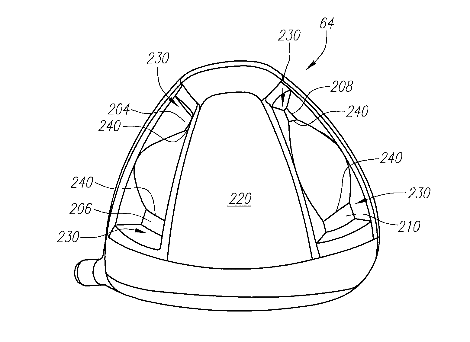
[0037]The present invention is generally directed to a multi-material golf club head that has interior structural means for generating rigidity in the head to help with acoustics or structural requirements, with minimal added mass. The structural means alters the sound emitted from the golf club head when the club strikes a golf ball.

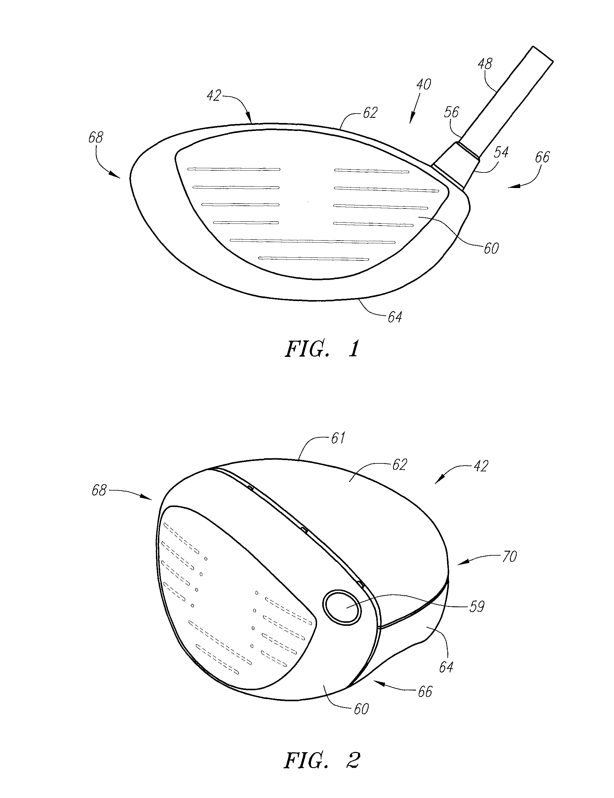
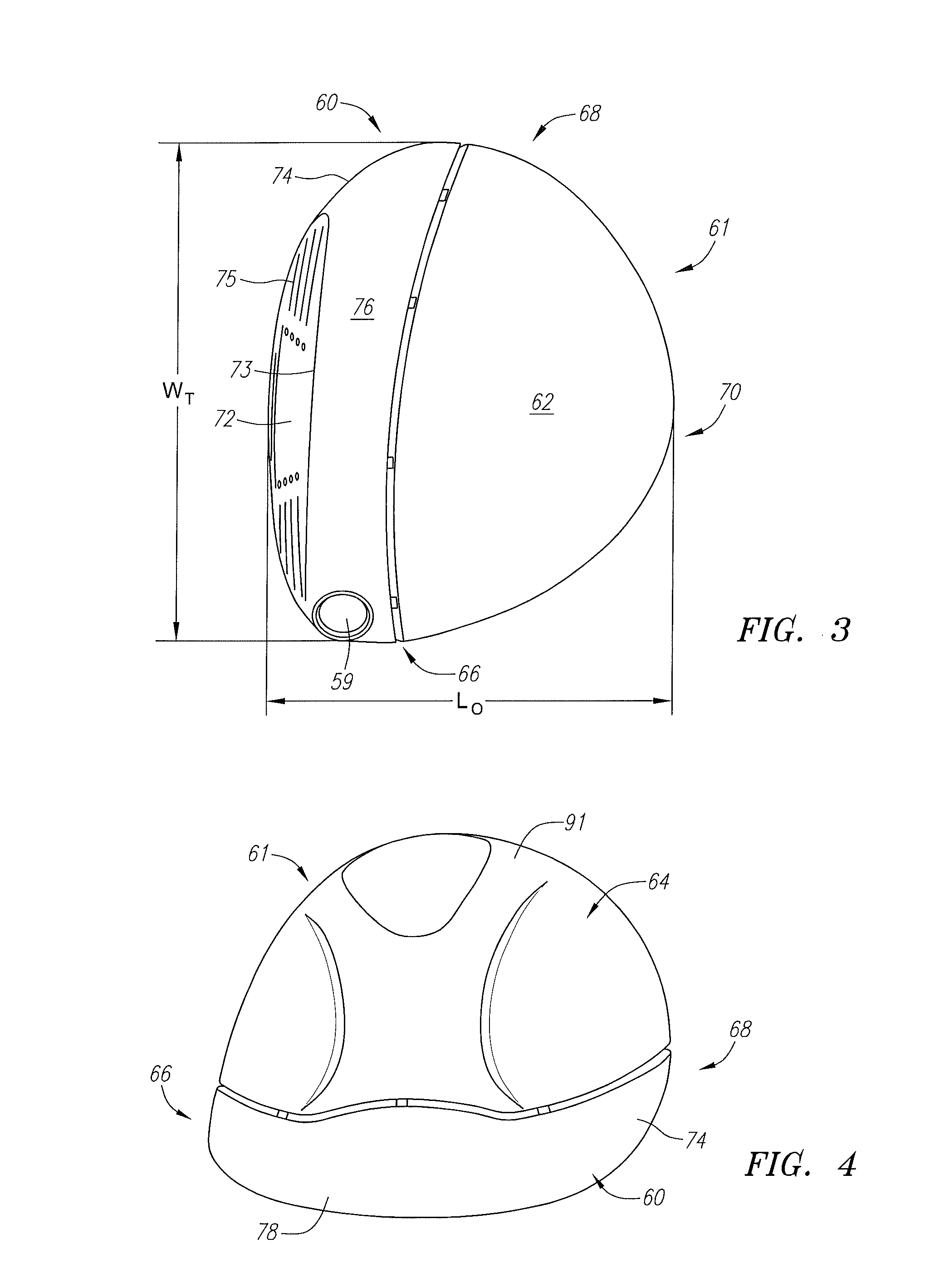
[0038]As shown in FIGS. 1-2, a golf club 40 is generally designated. The golf club 40 has a golf club head 42 with a hollow interior (not shown). As shown in FIG. 1, engaging the club head 42 is a shaft 48 that has a grip (not shown) at a butt end and is inserted 10 into a hosel 54 at a tip end 56. Alternatively, as shown in FIG. 2, the club head has a shaft receiving aperture 59 for receiving the shaft 48. The club head 42 is generally composed of three components: a face component 60; a crown 62; and a sole portion 64. The club head 42 also may optionally have a ribbon, skirt, or side portion disposed between the crown 62 and sole 64 portions. The gol...


PUM


Abstract

A golf club (40) having a club head (42) with a face component (60), an aft body (61), and a sound modifying sole and crown design is disclosed herein. The face component, which may be composed of a metal material, (60) has a striking area portion (72) and a return portion (74). The aft-body (61), which may be composed of a non-metal material such as composite or thermoplastic material, is composed of a crown portion (62) and a sole portion (64). The sound modifying design, which may include deep pockets or pillars extending from the sole portion (64) to the crown portion (62), alters the sound of the golf club head (42) when it impacts a golf ball.

Description

CROSS REFERENCES TO RELATED APPLICATIONS[0001]The present application claims priority to U.S. Provisional Patent Application No. 61 / 375,337, filed on Aug. 20, 2010. The present application also claims priority to U.S. Provisional Patent Application No. 61 / 376,632, filed on Aug. 24, 2010.STATEMENT REGARDING FEDERALLY SPONSORED RESEARCH OR DEVELOPMENT[0002]Not ApplicableBACKGROUND OF THE INVENTION[0003]1. Field of the Invention[0004]The present invention relates to a multiple-material golf club head having sole and crown configurations that generate rigidity in the head to help with acoustics and structural requirements with minimal added mass. More specifically, the present invention relates to a golf club head with face component composed of a metal material for a more efficient transfer of energy to a golf ball at impact, a non-metallic aft-body to control the mass distribution, and a connection between the sole and crown at a location other than the periphery of the club head, and...

Claims


Application Information

Patent Timeline
IPC IPC(8): A63B53/00
CPCA63B53/0466A63B2053/0416A63B2053/0458A63B2209/02A63B2053/045A63B2053/0433A63B2053/0462A63B53/04A63B2053/0425A63B2053/042A63B2053/0454A63B2053/0437A63B60/00A63B53/0416A63B53/0433A63B53/0437A63B53/045A63B53/0454A63B53/0458A63B53/0462A63B53/042A63B53/0425
Inventor DEMILLE, BRANDON D.CACKETT, MATTHEW T.
Owner CALLAWAY GOLF CO
Why Eureka
Try Eureka