Adjustable offset bushing

a bushing and offset technology, applied in the field of orthopaedic instruments, can solve the problems of centrally located stems that interfere with the tibial or femoral cortex, and do not allow a proper positioning of the base portion of the implan

Active Publication Date: 2013-07-23
HOWMEDICA OSTEONICS CORP
View PDF19 Cites 27 Cited by
  • Summary
  • Abstract
  • Description
  • Claims
  • Application Information

AI Technical Summary

Problems solved by technology

However, the centrally located stem may interfere with the tibial or femoral cortex as the surgeon attempts to center the implant on the tibia or the femur.
A centrally located stem on a tibial or femoral implant may therefore not allow a proper positioning of the base portion of the implant.

Method used


Image

  • Adjustable offset bushing
  • Adjustable offset bushing
  • Adjustable offset bushing

Examples


Embodiment Construction

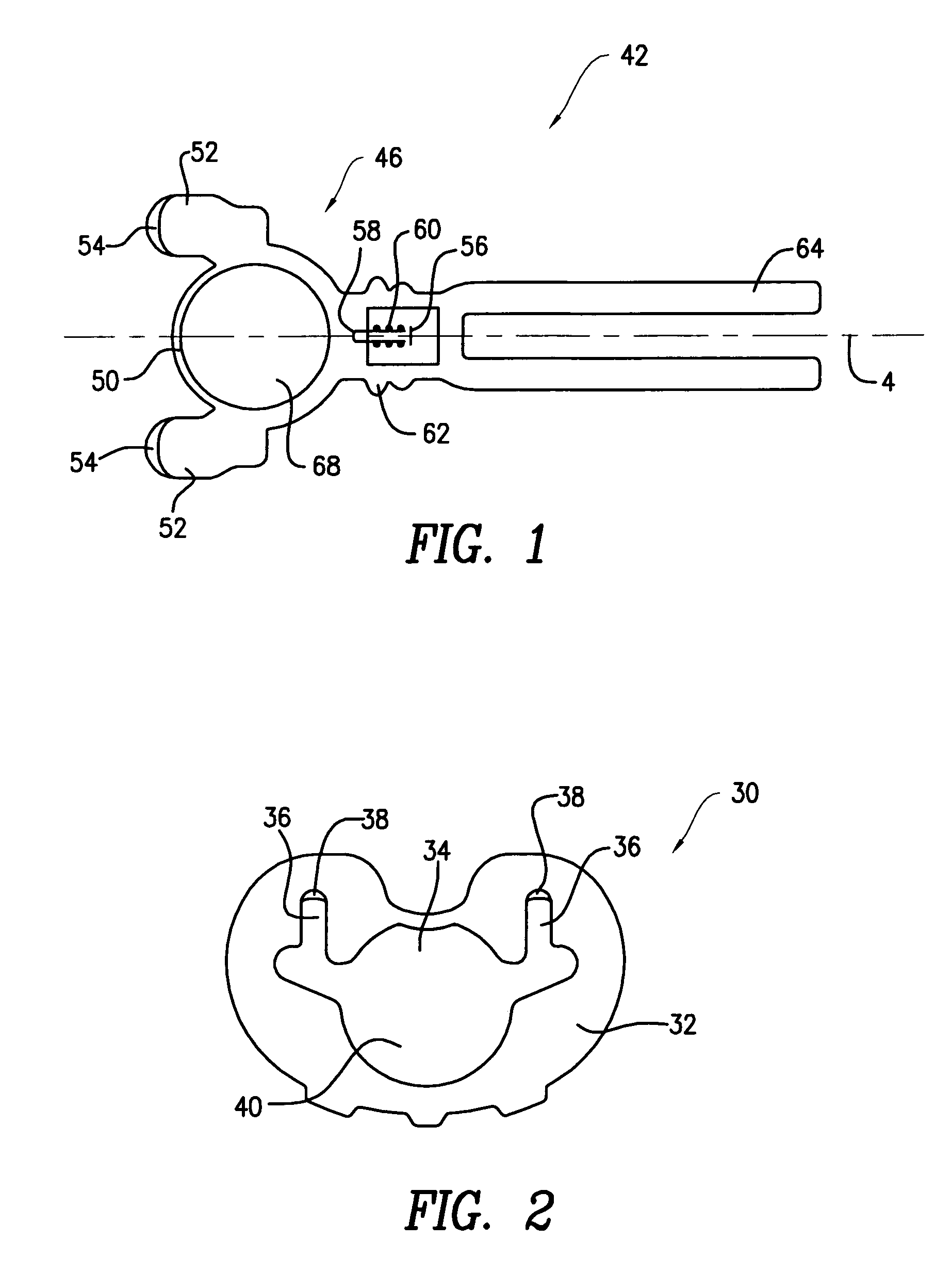
[0016]FIG. 1 shows a tibial template 30. Tibial template 30 has a body 32 and an opening 34 formed in body 32. Opening 34 includes branch sections 36 and ledges 38 formed in branch section 36. Tibial template 30 is to be located on resected proximal tibia in a manner that it optimally covers the resected surface of the tibia. A large substantially circular opening 40 is formed in tibial template 30. As used herein, when referring to bones or other parts of the body, the term “proximal” means closer to the heart and the term “distal” means more distant from the heart.

[0017]FIG. 2 shows a bushing guide 42. Bushing guide 42 has a handle 44 connected to a body 46. Body 46 has a circular opening 48 surrounded by a wall 50. Feet 52 project from wall 50. Feet 52 have a step 54 formed on each foot 52. Each step 54 engages under ledge 38 to attach bushing guide 42 to tibial template 30. When bushing guide 42 and tibial template 30 are assembled together, opening 40 and opening 48 are substan...


PUM


Abstract

An orthopaedic instrumentation having an intermediate piece that has an opening for receiving an intramedullary reference. The intermediate piece such as a tibial template or a cutting guide is located on the resected tibia or femur in a manner that it optimally covers the resected surface of the tibia or the femur. A bushing guide is provided for mounting on the intermediate piece. The bushing guide has a circular opening. An offset bushing is rotatably mounted in the opening in the bushing guide. A trigger flange is slidably mounted on the offset bushing. The trigger flange can slide back and forth relative to the offset bushing. An indicia is formed on the upper surface of trigger flange. The indicia when aligned with one of the indicia on the offset bushing body measures the offset of center of a bore in the trigger flange from center of the offset bushing. The offset bushing can rotate around its longitudinal axis in the opening in the bushing guide. Indicia on the offset bushing may be used to measure the orientation of the center of the hole in the trigger with respect to the center of bushing body.

Description

BACKGROUND OF THE INVENTION[0001]The present invention relates to orthopaedic instrumentation, and, more particularly, relates to adjustable offset bushing that allows easy determination of offset magnitude and orientation of an offset stem of a femoral component or a tibial baseplate.DESCRIPTION OF THE RELATED ART[0002]Conventional tibial and femoral prosthetic implants have a stem extension which is essentially centrally located relative to a base portion. However, the centrally located stem may interfere with the tibial or femoral cortex as the surgeon attempts to center the implant on the tibia or the femur. The intramedullary (IM) canal of the tibia or femur is often not centrally located relative to the peripheral edges of the tibia or the femur. A centrally located stem on a tibial or femoral implant may therefore not allow a proper positioning of the base portion of the implant. Thus, it is necessary to determine the offset for the stem on the tibial or femoral implant.[0003...

Claims


Application Information

Patent Timeline
Patent Type & Authority Patents(United States)
IPC IPC(8): A61F2/30
CPCA61B17/155A61F2002/4658A61F2002/4668
Inventor MCGOVERN, MICHAEL A.SIVADAS, SUJITLOGAN, SCOTT
Owner HOWMEDICA OSTEONICS CORP
Why Eureka
Try Eureka