
Flight controller management system with a backdrive monitor

a flight controller and monitor technology, applied in the field of aircraft, can solve the problems of increasing the workload of pilots for operating the aircraft, pilots may be unable to perform tasks, and the flight control system does not use mechanical linkages between the controller and the flight control surfa

Active Publication Date: 2013-07-23
THE BOEING CO
View PDF14 Cites 2 Cited by
  • Summary
  • Abstract
  • Description
  • Claims
  • Application Information

AI Technical Summary

Benefits of technology

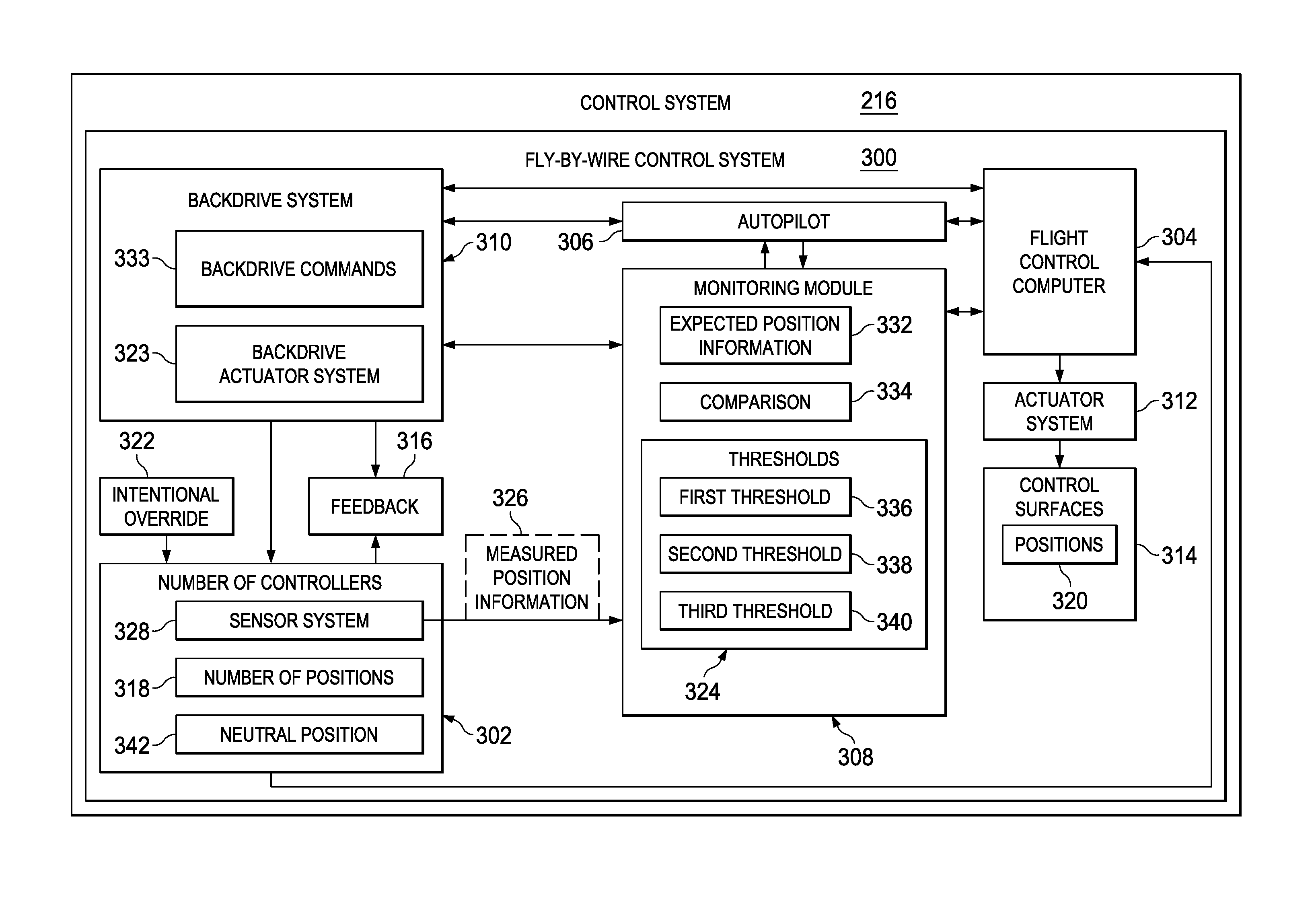
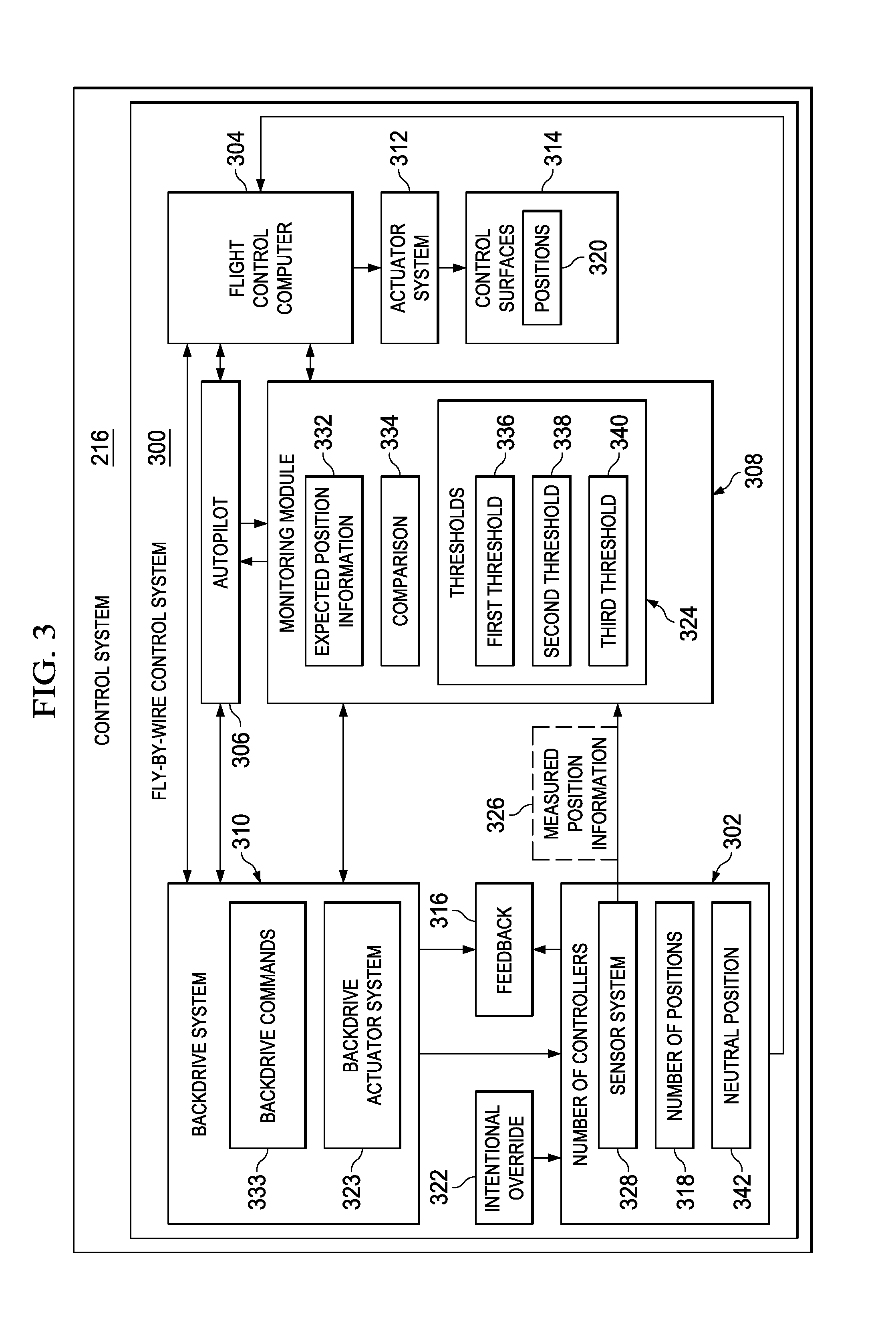
The patent describes an apparatus, method, and computer program product for managing an autopilot in a vehicle control system. The monitoring module identifies a difference between the measured position information for the controller and the expected position information, and compares it with pre-defined thresholds to form a comparison. Based on this comparison, the autopilot is managed to remain operating when the backdrive system is inoperable and an intentional override of the autopilot is absent. This allows for safe and reliable operation of the autopilot without needing constant supervision from the driver.

Problems solved by technology

Some types of flight control systems, however, do not use mechanical linkages between the controllers and the flight control surfaces.
As a result, the autopilot stops operating the aircraft, and the pilot has to take over operation of the aircraft.
In this manner, when the autopilot becomes unavailable, the workload of the pilot for operating the aircraft is increased.
In this manner, the pilot may be unable to perform tasks, such as, for example, navigation, communications, and / or other tasks as desired.
Further, when the pilot operates the aircraft for longer periods of time than expected, the pilot may become fatigued.
In this type of system, however, the use of additional actuators and wiring for the additional actuators increases the weight and cost of an aircraft.
Also, with additional actuators, more space is needed in the aircraft to accommodate these actuators.
Further, additional maintenance may be needed to replace or inspect the actuators.
The increased weight, cost, space used, and / or maintenance may be undesirable.

Method used


Image

  • Flight controller management system with a backdrive monitor
  • Flight controller management system with a backdrive monitor
  • Flight controller management system with a backdrive monitor

Examples


Embodiment Construction

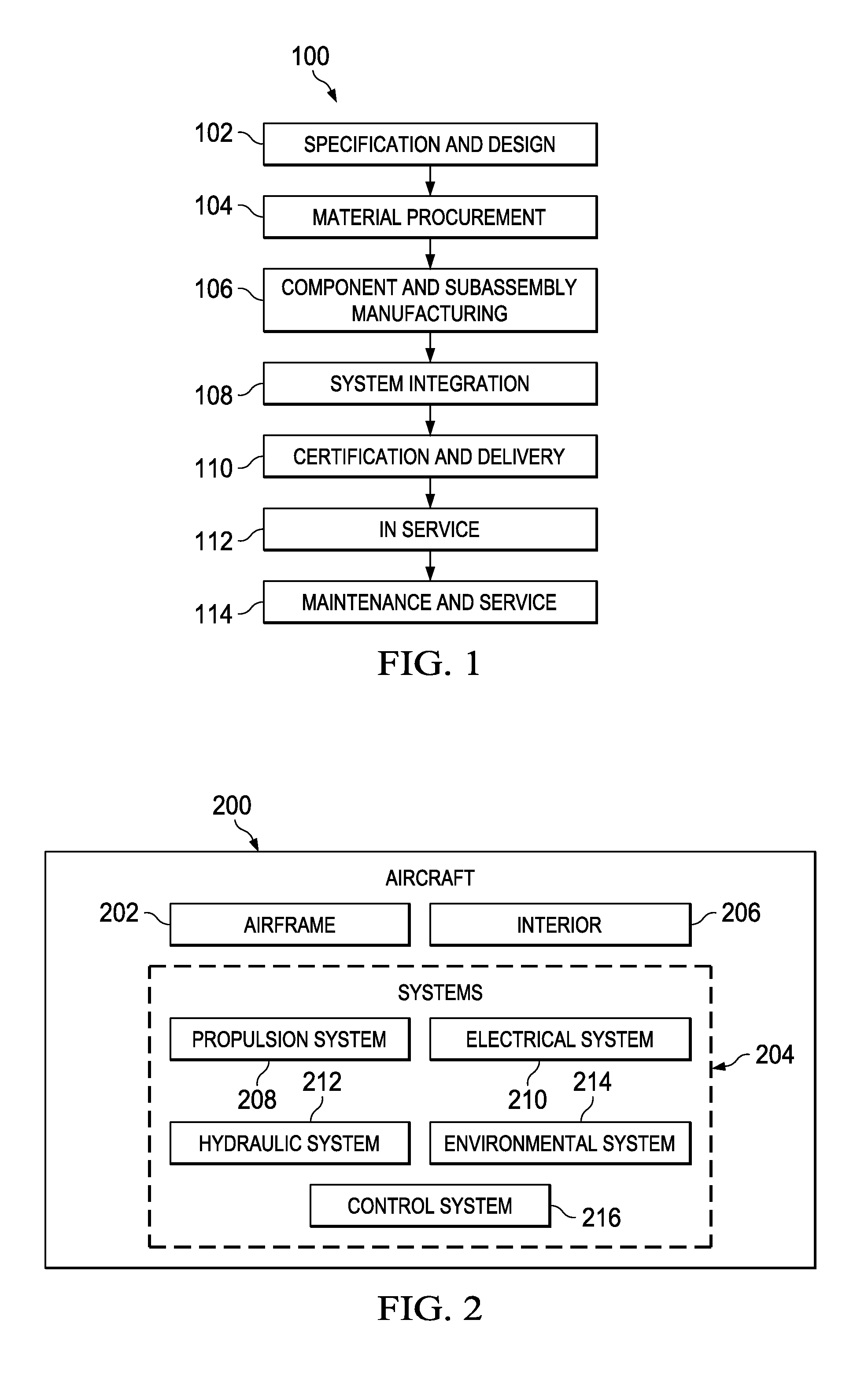
[0035]Referring more particularly to the drawings, advantageous embodiments of the disclosure may be described in the context of aircraft manufacturing and service method 100 as shown in FIG. 1 and aircraft 200 as shown in FIG. 2. Turning first to FIG. 1, an illustration of an aircraft manufacturing and service method is depicted in accordance with an advantageous embodiment. During pre-production, aircraft manufacturing and service method 100 may include specification and design 102 of aircraft 200 in FIG. 2 and material procurement 104.

[0036]During production, component and subassembly manufacturing 106 and system integration 108 of aircraft 200 in FIG. 2 takes place. Thereafter, aircraft 200 in FIG. 2 may go through certification and delivery 110 in order to be placed in service 112. While in service 112 by a customer, aircraft 200 in FIG. 2 is scheduled for routine maintenance and service 114, which may include modification, reconfiguration, refurbishment, rework, and other main...


PUM


Abstract

A method and apparatus for a monitoring module. The monitoring module is configured to identify a difference between measured position information for a controller and expected position information for the controller. The monitoring module is configured to compare the difference with thresholds for managing an autopilot in a control system of a vehicle to form a comparison. The monitoring module is configured to manage an operation of the autopilot based on the comparison such that the autopilot remains operating when a backdrive system is inoperative and an intentional override of the autopilot is absent.

Description

BACKGROUND INFORMATION[0001]1. Field:[0002]The present disclosure relates generally to aircraft and, in particular, to flight management control systems in aircraft. Still more particularly, the present disclosure relates to a method and apparatus for managing a flight control system in an aircraft.[0003]2. Background:[0004]An aircraft flight control system typically includes components, such as control surfaces, controllers in the cockpit, mechanisms to change the position of the flight control surfaces, and linkages connected to mechanisms that move the flight control surfaces. This type of flight control system provides a pilot with tactile and visual information regarding the position of the flight control surfaces. The tactile and visual information may occur through the orientation of the controllers in the cockpit.[0005]Many pilots are familiar with the use of these types of mechanical control systems. As a result, this familiarity provides a pilot with a certain level of psy...

Claims


Application Information

Patent Timeline
Patent Type & Authority Patents(United States)
IPC IPC(8): G05D1/00
CPCG05D1/0061B64C13/10B64C13/18B64C13/503B64D45/0005
Inventor KROGH, STEVEN BARRYBRESLEY, WILLIAM MILOCONNER, IAN M.LEVINE, BENJAMIN D.MINTEER-LEVINE, JASMINE BETHPETTIT, RYAN L.
Owner THE BOEING CO
Learn More