Imaging apparatus

a technology of cmos image sensor and image sensor, which is applied in the direction of radiation intensity measurement, instruments, x/gamma/cosmic radiation measurement, etc., can solve the problems of spatial aberration, difficult to set a new cmos area sensor in a correct place without misregistration, and the size of the cmos image sensor is generally smaller than the one before it, so as to achieve the effect of not reducing the frame ra

Inactive Publication Date: 2013-07-30
CANON KK
View PDF5 Cites 0 Cited by
  • Summary
  • Abstract
  • Description
  • Claims
  • Application Information

AI Technical Summary

Benefits of technology

[0010]The present invention relates to an imaging apparatus capable of acquiring an image less affected by misregistration of an area sensor and without reducing a frame rate.

Problems solved by technology

However, a size of the CMOS image sensor is generally smaller than the above-described size due to manufacturing process constraints.
However, when one of the arranged CMOS area sensors needs to be removed for some reason such as a defect, it is difficult to set a new CMOS area sensor in a correct place without misregistration.
For example, in the abovementioned scenario, if a new CMOS area sensor is not placed in the exact correct location, a spatial aberration is created because the new CMOS area sensor may not be properly aligned with the other CMOS area sensors.
Accordingly, when the CMOS area sensors are not aligned, an X-ray image obtained by the X-ray imaging apparatus using such CMOS area sensors may have pixel misregistration.
Correction of the pixel misregistration by image processing using software is not practical since a frame rate will be reduced.
Thus, it is difficult to repair the area sensors which are put together.

Method used


Image

  • Imaging apparatus
  • Imaging apparatus
  • Imaging apparatus

Examples


Embodiment Construction

[0029]Various exemplary embodiments, features, and aspects of the invention will be described in detail below with reference to the drawings.

[0030]A first exemplary embodiment of the present invention will be described.

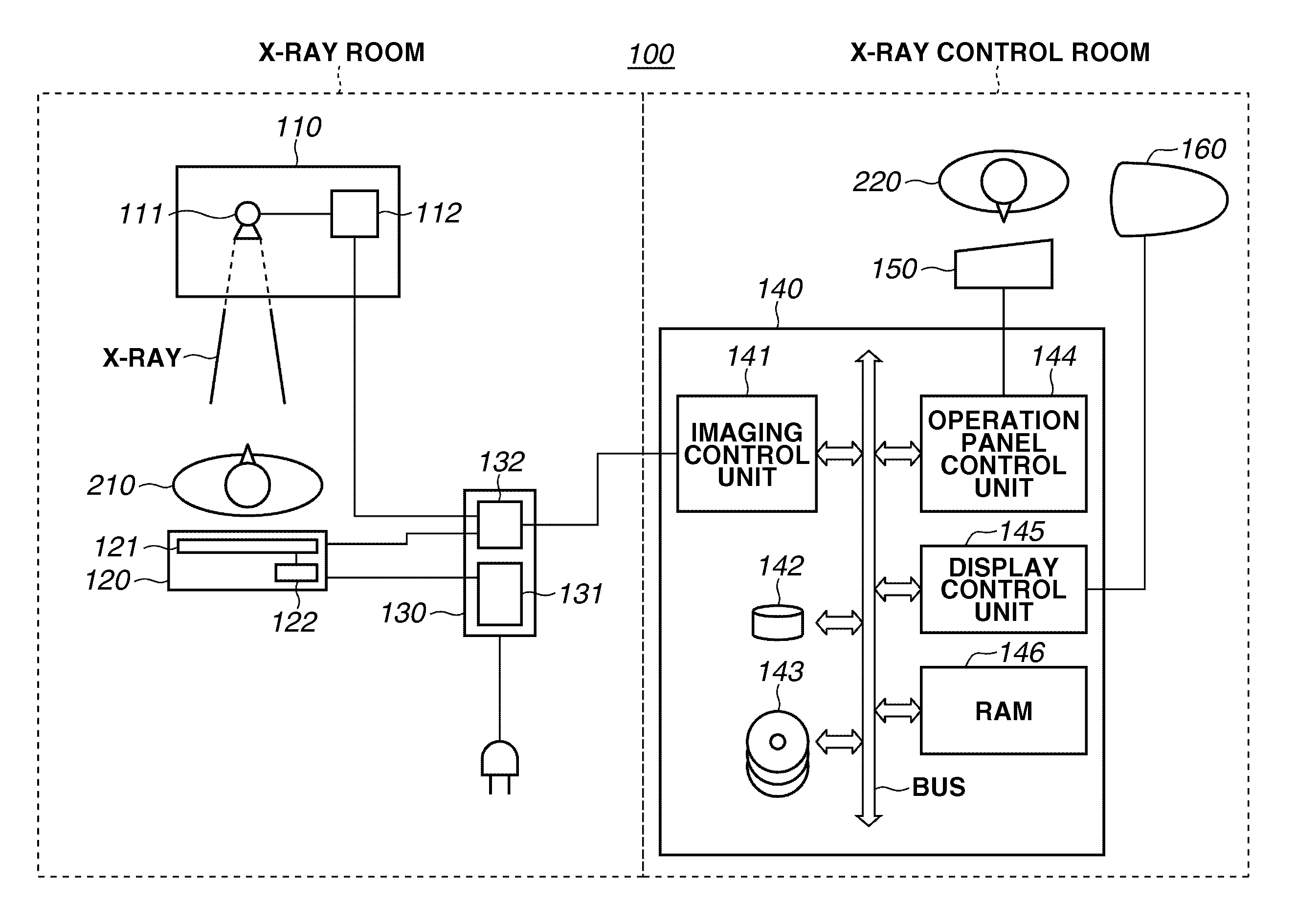
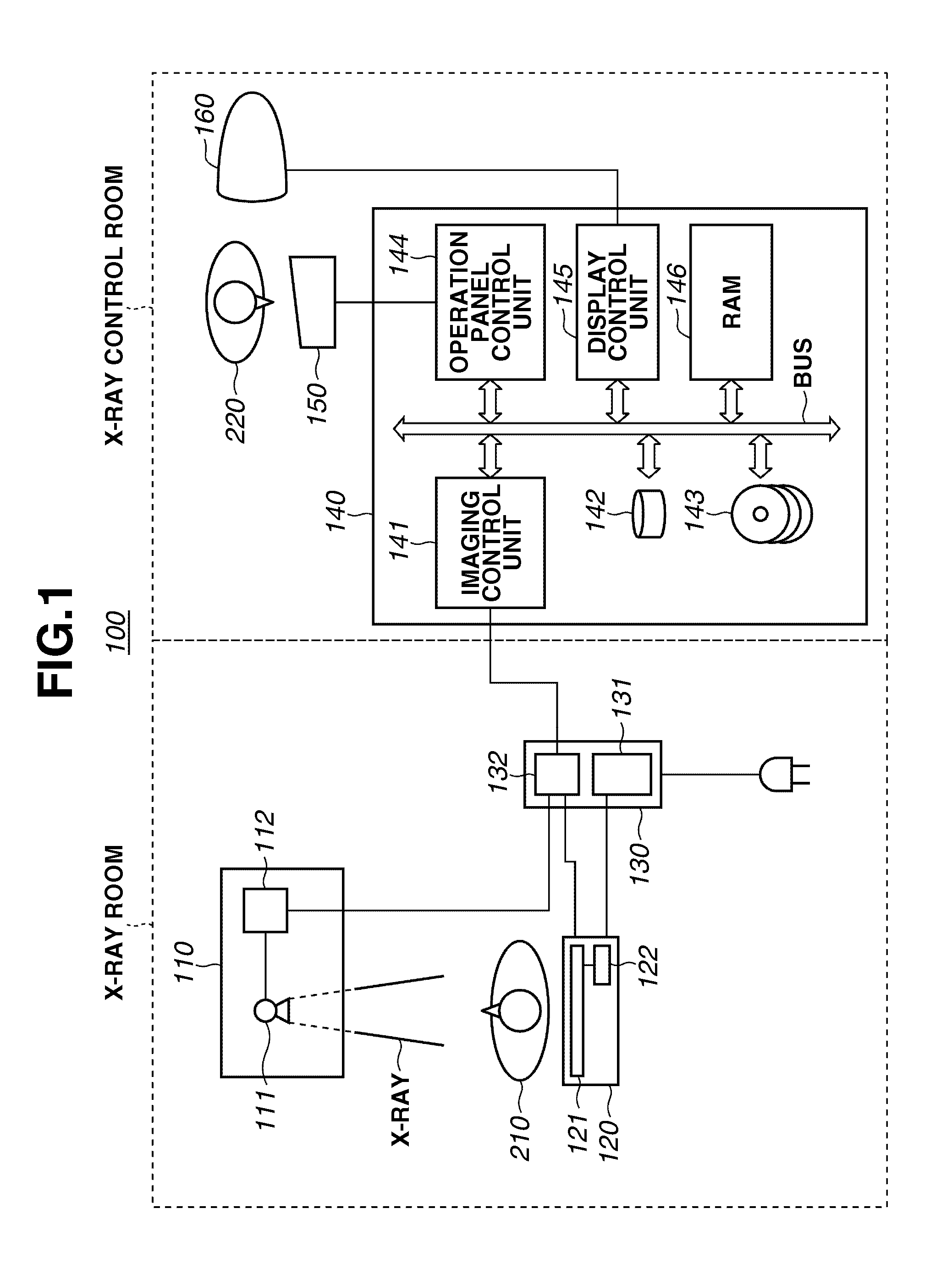
[0031]FIG. 1 is a schematic drawing illustrating an example of a configuration of an X-ray imaging system (radiation imaging system) 100 according to the first exemplary embodiment of the present invention. The X-ray imaging system 100 includes two rooms, an X-ray room and an X-ray control room.

[0032]As illustrated in FIG. 1, the X-ray imaging system 100 includes an X-ray generating apparatus 110, an X-ray imaging apparatus 120, an external unit 130, a system control apparatus 140, an operation panel 150, and a display 160.

[0033]According to the example illustrated in FIG. 1, the X-ray generating apparatus 110, the X-ray imaging apparatus 120, and the external unit 130 are set in the X-ray room, and the system control apparatus 140, the operation panel 150, and the di...


PUM


Abstract

An imaging apparatus includes an image sensor in which a plurality of area sensors arranged adjacent to each other to form an image sensor. A control circuit controls timing for reading out image data from each of the plurality of the area sensors based on area sensor arrangement information concerning the arrangement of each of the plurality of the area sensors.

Description

BACKGROUND OF THE INVENTION[0001]1. Field of the Invention[0002]The present invention relates to an imaging apparatus which includes an image sensor. More particularly, the present invention relates to an imaging apparatus that acquires radiation image data by using an image sensor according to a radiation ray transmitted through an object.[0003]2. Description of the Related Art[0004]In recent years, an X-ray imaging system that captures an X-ray image of an object as a digital image has been developed. Compared to conventional X-ray photograph systems that use a silver halide photograph, the X-ray imaging system is more practical in that it can record an X-ray image of an extremely wide exposure range.[0005]More specifically, according to the X-ray imaging system, an X-ray of an extremely wide dynamic range is photoelectrically converted into an electric signal by, for example, phosphor. The obtained electric signal is read out and further converted into a digital signal.[0006]Acco...

Claims


Application Information

Patent Timeline
Patent Type & Authority Patents(United States)
IPC IPC(8): G01T1/29
CPCG01T1/2018G01T1/20184
Inventor NIWA, HIROAKI
Owner CANON KK
Why Eureka
Try Eureka