Image sensing apparatus, method thereof, storage medium and computer program

a technology storage medium, which is applied in the field of image sensing apparatus, a storage medium and a computer program, can solve the problems of power consumption, lsi chip area increase, and frame rate of moving image drop, so as to achieve the effect of not lowering the frame rate of moving imag

Inactive Publication Date: 2006-11-23
CANON KK
View PDF13 Cites 35 Cited by
  • Summary
  • Abstract
  • Description
  • Claims
  • Application Information

AI Technical Summary

Benefits of technology

[0005] In view of the aforementioned problems, an object of the present invention is to allow parallel processing of a moving image and a still image without lowering a frame rate of the moving image.

Problems solved by technology

As for the conventional examples, however, No. 2001-326896 has problems that its LSI chip area increases because it is arranged to have multiple image processing blocks for the still images and for the moving images.
Also, power consumption increases because it performs simultaneous parallel image processing of the moving image and still image.
As for No. 2003-158653, there is a problem that the frame rate of the moving image lowers on capturing the still image while storing the moving image.

Method used


Image

  • Image sensing apparatus, method thereof, storage medium and computer program
  • Image sensing apparatus, method thereof, storage medium and computer program
  • Image sensing apparatus, method thereof, storage medium and computer program

Examples


first embodiment

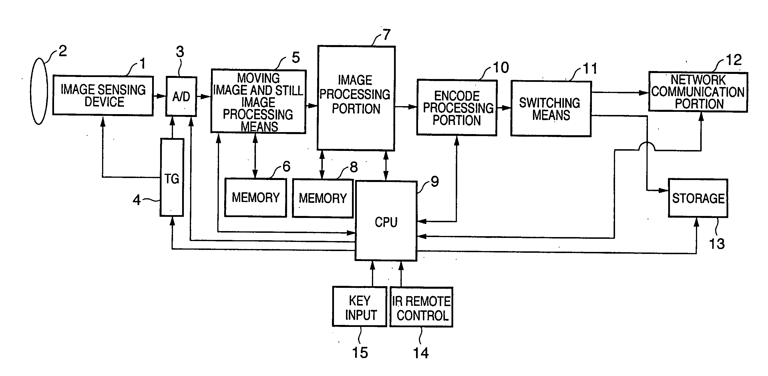
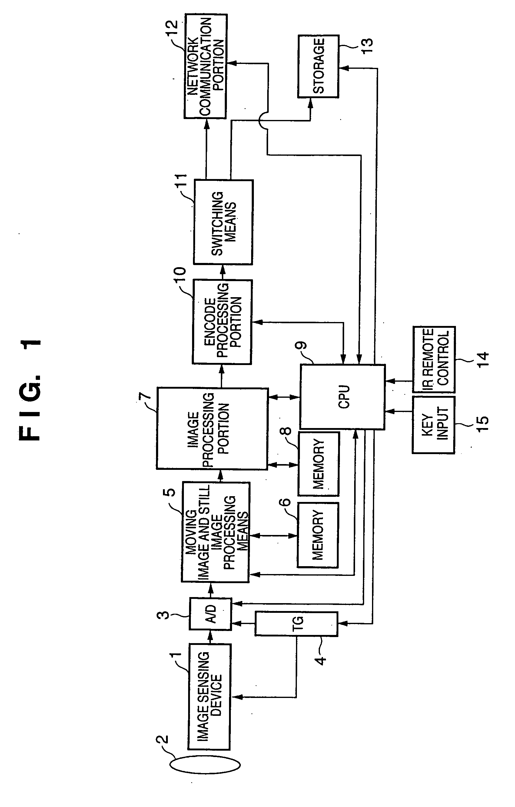
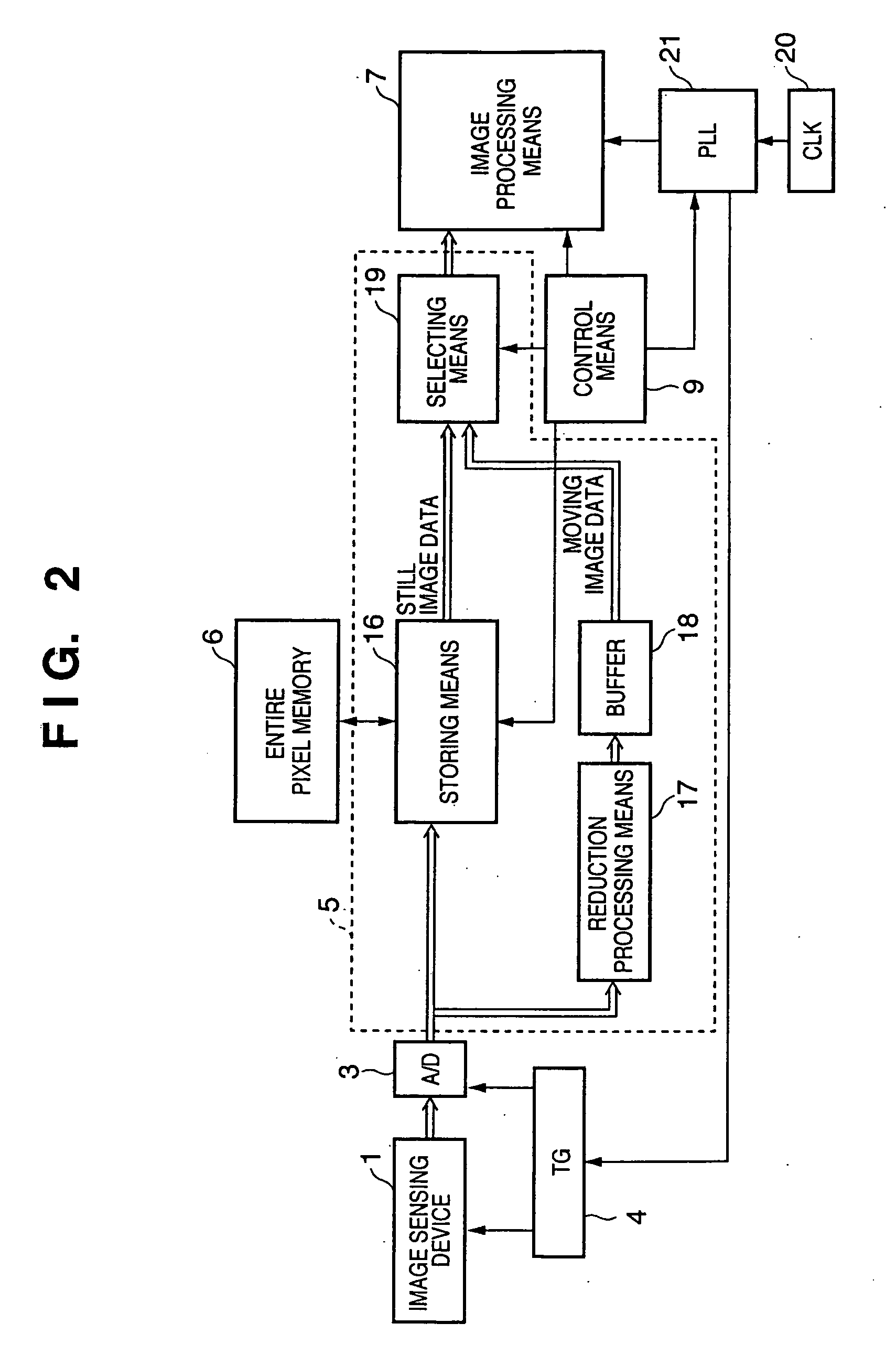
[0033] FIGS. 1 to 3 are diagrams representing the first embodiment of the present invention. FIG. 1 is a block diagram representing the entire overview of an image sensing apparatus of the present invention. FIG. 2 is a block diagram showing characteristics relating to the first embodiment of the present invention. FIG. 3 is a timing chart of various processes representing the characteristics of this embodiment.

[0034] In configuration order of FIG. 1, reference numeral 1 indicates an image sensing device which is a photoelectric conversion element. Though not particularly limited as the image sensing device, it represents the image sensing device such as a CCD or a CMOS sensor, which is the image sensing device capable of reading out all the pixels within one frame period configuring a moving image as the first embodiment. Reference numeral 2 indicates a lens. Reference numeral 3 indicates an AD conversion portion in control of AD conversion for digital-converting analog imaging da...

second embodiment

[0068]FIGS. 1, 4 and 5 are diagrams representing a second embodiment of the present invention. A block diagram showing an image sensing apparatus of the second embodiment is the same configuration as that described in FIG. 1 of the first embodiment. FIG. 4 is a block diagram showing the characteristics relating to the second embodiment of the present invention. FIG. 5 is a timing chart representing the characteristics of this embodiment.

[0069] The configuration of FIG. 4 is a block diagram corresponding to reference numerals 1 to 21 of FIG. 2 described in the first embodiment, which is different therefrom in that the configuration does not have the buffer memory 18 described in FIG. 2. The structure surrounded by a dot line in FIG. 4 corresponds to the moving image and still image processing means 5. The blocks of FIGS. 1 and 4 have the same functions and configurations as the blocks of FIGS. 1 and 2 described in the first embodiment, and so a description thereof will be omitted.

[...

third embodiment

[0092]FIGS. 6, 7 and 8 are diagrams representing a third embodiment of the present invention. FIG. 6 is a block diagram showing an overview of this embodiment. FIG. 7 is a block diagram showing the characteristics relating to this embodiment. FIG. 8 is a timing chart of various processes representing the characteristics of this embodiment.

[0093] In FIG. 6, elements having the same functions as FIG. 1 are given the same numbers as those in FIG. 1. In FIG. 6, reference numeral 1 indicates an image sensing device which is a photoelectric conversion element. Though not particularly limited as the image sensing device, it represents the image sensing device such as a CCD or a CMOS sensor, which is the image sensing device capable of reading out all the pixels within one frame period configuring a moving image according to this embodiment. Reference numeral 2 indicates a lens.

[0094] Reference numeral 3 indicates an AD conversion portion in control of AD conversion for digital-converting...


PUM


Abstract

To provide an image sensing apparatus and the like comprising: imaging means; image reducing means for reducing an image size from imaging data obtained from the imaging means; moving image configuring means for rendering an image reduced by the image reducing means as a moving image; image processing means for image-processing image data; network communication means; and image data storing means for storing frame image data obtained from the imaging means in response to a control instruction from outside while taking a moving image, and wherein: the image data stored in the image data storing means is image-processed by dividing it into non-operating periods of moving image processing per frame configuring the moving image. And to allow parallel processing of a moving image and a still image without lowering a frame rate of the moving image.

Description

FIELD OF THE INVENTION [0001] The present invention relates to an image sensing apparatus, a method thereof, a storage medium and a computer program, and in particular, to a suitable technology for processing a moving image and a still image in parallel for instance. BACKGROUND OF THE INVENTION [0002] A conventional image sensing apparatus, which captures a high density still image when instructed to capture a still image by external manipulation while sensing a moving image, is provided. For example, the apparatus has multiple image processing systems, one for still and another for moving image, and processes a still image in a still image system. The still image to be processed is constructed with several frames by sequentially processing area portions of a screen separated by a frame period or a field period, refer to Japanese Patent Laid-Open No. 2001-326896. [0003] For another example, an apparatus having an image sensing device for reading out moving and still images in separa...

Claims


Application Information

Patent Timeline
Patent Type & Authority Applications(United States)
IPC IPC(8): A61B5/05
CPCH04N5/232H04N5/23206H04N5/23245H04N9/8047H04N9/7921H04N9/8042H04N5/772H04N23/667
Inventor MASAKI, JUNYA
Owner CANON KK
Why Eureka
Try Eureka